PowerFlex SCR Bus Supply Firmware Version 1.
Important User Information Solid state equipment has operational characteristics differing from those of electromechanical equipment. Safety Guidelines for the Application, Installation and Maintenance of Solid State Controls (Publication SGI-1.1 available from your local Rockwell Automation sales office or online at http:// www.rockwellautomation.com/literature) describes some important differences between solid state equipment and hard-wired electromechanical devices.
Summary of Changes The information below summarizes the changes made to this manual since its last release (March 2011): Description of Changes Page In Chapter 1 in the “1000A SCR Bus Supply Flexibility” section: • Added information and a table at the beginning to show which conversions are possible and which are not possible. • In the “Converting Master Unit to Slave Unit” subsection, added new steps 3 and 4. • Deleted subsection “Converting Slave Unit to Master Unit” subsection.
soc-ii Summary of Changes PowerFlex SCR Bus Supply User Manual Publication 20S-UM001G-EN-P
Table of Contents Preface Overview Who Should Use this Manual? . . . . . . . . . . . . . . . . . . . . . . . . . . . . . . . . . . . . . . . . . . . . . Reference Documentation . . . . . . . . . . . . . . . . . . . . . . . . . . . . . . . . . . . . . . . . . . . . . . . . Rockwell Automation Support . . . . . . . . . . . . . . . . . . . . . . . . . . . . . . . . . . . . . . . . . . . . . Conventions Used in This Manual . . . . . . . . . . . . . . . . . . . . . . . . . . . . . . . . . . . . . . . . . .
ii Table of Contents PowerFlex SCR Bus Supply User Manual Publication 20S-UM001G-EN-P
Preface Overview The purpose of this manual is to provide you with the basic information needed to install, start up, and troubleshoot the PowerFlex SCR Bus Supply.
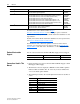
P-2 Overview For: PowerFlex® 700H Drive PowerFlex® 700S Drive PowerFlex® 750-Series AC Drive Refer to: PowerFlex 700H Installation Instructions PowerFlex 700H Programming Manual PowerFlex 700S with Phase I Control Installation Manual (Frames 1…6) PowerFlex 700S with Phase I Control Installation Manual (Frames 9 and 10) PowerFlex 700S with Phase I Control User Manual (All Frame Sizes) PowerFlex 700S with Phase I Control Reference Manual PowerFlex 700S with Phase II Control Installation Manual (Frames 1…6
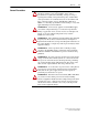
Overview General Precautions ! ! ! ! ! ! ! P-3 ATTENTION: This Bus Supply contains ESD (Electrostatic Discharge) sensitive parts and assemblies. Static control precautions are required when installing, testing, servicing or repairing this assembly. Component damage may result if ESD control procedures are not followed. If you are not familiar with static control procedures, refer to Allen-Bradley publication 8000-4.5.
P-4 Overview Catalog Number Explanation Position Number 5-7 8 1-3 4 20S D 400 a b c 9 10 N E N d e f a Product Code 20S Type PowerFlex SCR Bus Supply b Voltage Rating Code D F Input Voltage 400/480V AC 600/690V AC Phase 3 3 DC Output 540 - 650V DC 675 - 930V DC c Current Rating Code 400 600 1k0 Output 400A, 400/480V 600A, 400/480V 1000A, 400/480/600/690V d Enclosure Code N Rating Open / IP00 Conformal Coating No e Documentation & Shipping Carton Code User Manual E English Car
Overview P-5 Descriptions and Schematic The SCR Bus Supply is a single-direction power converter for the front end of common DC bus drive systems. It converts the incoming 3-phase AC line Diagrams voltage to a common DC bus voltage. Figure P.
P-6 Overview Figure P.
Overview P-7 Figure P.
P-8 Overview Figure P.4 1000A SCR Bus Supply Slave Unit Schematic Diagram +DC 2 F7-11 PE V1 L1 L2 L3 L5 L4 ➌ L1 V3 5 4 3 F1 2 2 5 4 V5 5 4 3 3 F4 F3 L2 ➊ F6 L3 F5 ➍ F2 2 GND 12 11 10 9 8 7 6 5 4 2 1 0 115 X1 >°C F12 2 V4 ➋ 2 V6 5 4 3 3 + + N M L1 ➑ From Gate Driver X6 on the Master (Figure P.
Chapter 1 Installation/Wiring This chapter provides information on the installation and wiring of the PowerFlex SCR Bus Supply.
1-2 Installation/Wiring Opening the Cover 1. Remove the four fastening screws. (The steel sheet cover will stay in place, even in the vertical position.) 2. Hold the cover with both hands at the bottom, and lift it upward about 2 cm (0.8 in.) and away from the enclosure (Figure 1.1). Figure 1.
Installation/Wiring Minimum Mounting Clearances 1-3 The cabinet air inlet and outlet areas for each SCR Bus Supply must be a minimum of 200 cm2 (31 in.2). The length-to-width ratio must not exceed 4:1. Figure 1.2 Mounting Clearances Air Outlet Air Outlet PowerFlex SCR Bus Supply PowerFlex SCR Bus Supply 150 mm (6 in.) 120 mm (4.7 in.) Air Flow Air Flow 120 mm (4.7 in.) 300 mm (12 in.) Air Flow below fan Air Inlet Air Inlet Refer to Appendix A for detailed dimension information.
1-4 Installation/Wiring AC Supply Source Considerations The PowerFlex SCR Bus Supply is suitable for use on a circuit capable of delivering a short circuit rating up to a maximum of 85,000 rms symmetrical amperes. If a Residual Current Detector (RCD) is used as a system ground fault monitor, only Type B (adjustable) devices should be used to avoid nuisance tripping.
Installation/Wiring General Grounding Requirements 1-5 The Safety Ground terminal (PE) must be connected to the building grounding scheme. Ground impedance must conform to the requirements of national and local industrial safety regulations and/or electrical codes. The integrity of all ground connections should be periodically checked. For installations within a cabinet, a single safety ground point or ground bus bar connected directly to building steel should be used.
1-6 Installation/Wiring Minimum Capacitance In order to commission and test the SCR Bus Supply, a minimum capacitance is required. The design of the final installation must assure that the minimum capacitance is connected whenever the bus supply is to be enabled. If this minimum capacitance is not present, the bus supply internal fault detection circuit will interpret the condition as a DC bus short and stop pulse firing.
Installation/Wiring Fusing 1-7 The 400A and 600A PowerFlex SCR Bus Supplies have built-in AC line and DC bus fuses. The 1000A unit has six in-path fuses which simultaneously protect AC and DC paths. All units are equipped with fuse trip indicator switches. For a list of recommended replacement fuses, refer to these pages. SCR Bus Supply See Page… 400A A-15 600A A-17 1000A A-19 Power Wiring ! ATTENTION: National Codes and standards (NEC, VDE, BSI, etc.
1-8 Installation/Wiring Power Connection Bus Bars and Terminals L2 L1 ➋ L3 DC+ 400A Unit Bus Bar and Terminal Locations for Customer Wiring DC- Figure 1.4 ➊ ➌ ➍ Table 1.C 400A Unit Power Connection Specifications Recommended Minimum Size Item Description Copper Bus Bars (1) ➊ AC Line Input L1, L2, L3 40 x 5 mm 40 x 5 mm (1.57 x 0.2 in.) with single 14 mm (0.55 in.) diameter hole for customer terminal 120 mm2 (or 2 x 50 mm2) ➋ DC Bus DC+, DC- 40 x 5 mm (1.57 x 0.2 in.
Installation/Wiring 600A Unit Bus Bar and Terminal Locations for Customer Wiring DC+ ➋ L3 L2 L1 DC- Figure 1.5 1-9 ➊ ➌ ➍ Table 1.D 600A Unit Power Connection Specifications Recommended Minimum Size Item Description Copper Bus Bars (1) Bus Bar Wire ➊ AC Line Input L1, L2, L3 50 x 5 mm (1.97 x 0.2 in.) with two 14 mm (0.55 in.) diameter holes for customer terminal 50 x 5 mm 240 mm2 (or 2 x 95 mm2) ➋ DC Bus DC+, DC- 50 x 5 mm (1.97 x 0.2 in.) with two 14 mm (0.55 in.
Installation/Wiring 1000A Unit Bus Bar and Terminal Locations for Customer Wiring L1 DC+ DC- ➋ L3 Figure 1.6 L2 1-10 ➊ ➌ ➍ Table 1.E 1000A Unit Power Connection Specifications Recommended Minimum Size Item Description Copper Bus Bars (1) ➊ AC Line Input L1, L2, L3 50 x 10 mm (1.97 x 0.39 in.) with 50 x 10 mm two 14 mm (0.55 in.) diameter (or 80 x 5 mm) holes for customer terminal ➋ DC Bus DC+, DC- 60 x 10 mm (2.36 x 0.39 in.) with 60 x 10 mm 2 x 300 mm2 two 14 mm (0.55 in.
Installation/Wiring Important points to remember about control wiring: • Use Copper wire only. Wire gauge requirements and recommendations are based on 75 °C (168 °F). Do not reduce wire gauge when using higher temperature wire. • Wire with an insulation rating of 600V or greater is recommended. • Control wires outside the cabinet should be separated from power wires by at least 0.3 meters (1 foot). Table 1.F Control Terminal Specifications Wire Size Range (1) Item Name Maximum Minimum Torque ➍ 2.
1-12 Installation/Wiring Drive Run Interlock To protect the Bus Supply from overtemperature, the normally closed contacts (Bus Supply Overtemperature - terminals 10 and 11) should be wired to either the AC line input contactor for the Bus Supply or the Run interlock circuit (enable input) of each connected drive. This ensures that the drives are stopped in case of Bus Supply Overtemperature. Control Wiring Example Figure 1.
Installation/Wiring 1-13 active front end that is used only as a regenerative brake unit. The PowerFlex SCR Bus Supply will then deliver the required motoring power and the RGU/AFE will provide the possibility to feed the regenerative energy back to the AC power line. The auto-voltage limitation (allowing the SCRs to phase back) associated with high AC line will be disabled. The left (RGU/AFE) jumper position provides the best protection for parellel SCR and RGU/AFE operation.
1-14 Installation/Wiring Disconnecting MOVs The PowerFlex SCR Bus Supply contains protective MOVs that are referenced to ground. To prevent damage, the MOVs should be disconnected from ground if the Bus Supply is installed on any non-solid grounded distribution system where the line-to-ground voltages on any phase could exceed 125% of the nominal line-to-line voltage. To disconnect the MOVs from ground, remove the jumper (12-GND) on the control terminal block shown in Figure 1.7 on page 1-11.
Installation/Wiring 1-15 Parallel Connection of Slave Up to four 1000A PowerFlex SCR Bus Supply Slave units may be connected in parallel with one 1000A Master. The derate for each additional Units slave is 5% plus 5% for the master. Thus, the maximum possible output rating without altitude or ambient derating is 4750 Amps (0.95 x 5 x 1000 amps) at 40 °C. Figure 1.
1-16 Installation/Wiring 1000A SCR Bus Supply Flexibility The 1000A SCR Bus Supply can be converted in the following ways. 1000A SCR Bus Supply Convert to… Standalone Master No Convert from: Standalone Master Yes Slave No Slave No Yes No Because of numerous internal changes (components, cables, and hardware) the following conversions are not allowed: • • • • Standalone to master Standalone to slave Slave to standalone Slave to master NOTE: See Figure A.
Installation/Wiring 1000A SCR Bus Supply Redundancy 1-17 It is not recommended to install parallel master SCR Bus Supplies. The reason is that there is nothing to synchronize the SCR gate firing between the precharge printed circuit boards in separate SCR Bus Supplies. Each precharge board has circuitry designed to energize the DC bus, which has little to no impedance to limit the inrush current. This DC bus charging synchronization could lead to power device failure.
1-18 Installation/Wiring SCR Bus Supply 12-Pulse Configuration Standalone or master/slave SCR Bus Supplies can be used on applications that use a 12-pulse transformer to minimize power line harmonics. Important: Be sure to select the slow ramp time (see Jumper Settings on page 1-12). Figure 1.12 shows a recommended 12-pulse system configuration with optional slave SCR Bus Supplies. Figure 1.
Installation/Wiring CE Conformity 1-19 Conformity with the Low Voltage (LV) Directive and Electromagnetic Compatibility (EMC) Directive has been demonstrated using harmonized European Norm (EN) standards published in the Official Journal of the European Communities. The PowerFlex SCR Bus Supply complies with the EN standards listed below when installed according to the User Manual. CE Declarations of Conformity are available online at: http://www.ab.
1-20 Installation/Wiring • Conformity of the drive with CE EMC requirements does not guarantee an entire machine installation complies with CE EMC requirements. Many factors can influence total machine/installation compliance. Essential Requirements for CE Compliance Conditions 1…5 listed below must be satisfied for the PowerFlex SCR Bus Supply to meet the requirements of EN61800-3. 1. Bus Supply and inverter must be PowerFlex type and CE compatible. 2.
Chapter 2 Start Up/Troubleshooting This chapter provides the necessary information for the start up and troubleshooting of the PowerFlex SCR Bus Supply. Topic Start-Up Precharge Board LED Indicators Troubleshooting ! ! ! Page 2-2 2-4 2-6 ATTENTION: Power must be applied to the SCR Bus Supply and the Inverter to perform the following start-up procedure. Some of the voltages present are at incoming line potential.
2-2 Start Up/Troubleshooting Start-Up Before Applying Power to the Bus Supply ❏ 1. Verify that the minimum of one Inverter is connected to the DC bus. ❏ 2. Confirm that all inputs are connected to the correct terminals and are properly torqued. ❏ 3.
Start Up/Troubleshooting 2-3 ❏ 9. Verify that the SPARE 1 and SPARE 2 jumpers on the Precharge Board shown in Figure 2.1 are set to appropriate positions for the application. (Refer to Jumper Settings on page 1-12 and Figure 1.9 on page 1-13 for more information). ❏ 10. Verify that the jumper between control terminals 12 and GND (Figure 1.7 on page 1-11) is present on grounded supply lines (default) or is removed on non-solid grounded supply lines.
Start Up/Troubleshooting Precharge Board LED Indicators The three LEDs on the Precharge Board are visible through a small slot in the SCR Bus Supply cover. The 400A unit cover has one slot. The 600A unit cover has two slots but only the lower slot is used to view the LEDs. Since the Precharge Board for the 1000A unit is mounted either on the lower carrier plate (on Single Units) or on the upper carrier plate (on Master Units), the corresponding lower or upper slot is used to view the LEDs.
Start Up/Troubleshooting 2-5 Table 2.A Precharge Board LED Indicators Name Color State Description POWER OK Green Steady Illuminates when precharge board power supply is operational. ALARM Yellow Flashing The number [n] of flashes (see flashing pattern in Figure 2.
2-6 Start Up/Troubleshooting Troubleshooting Table 2.B Possible Faults and Corrective Actions Fault Cause Heat sink Heat sink temperature Overtemperature exceeds maximum rating Corrective Action 1. Verify that maximum ambient temperature has not been exceeded. 2. Check Overtemperature Switch (N.C. contacts) at control terminals 10 and 11. 3. Check 115V AC supply input voltage at control terminals 0 and 115. 4. Check blower for correct operation. 5. Check for excess load on the bus supply. 6.
Start Up/Troubleshooting 2-7 Important: Complete the tests listed in Table 2.C without power applied to the SCR Bus Supply. Table 2.C Control Terminal Block Continuity Test Conditions Test Condition Possible Cause N.C. contact on control terminals 6 and 7 is open 400A and 600A Unit: Open 1. Check for evidence of power module failure (see Step 3 in Start-Up on page 2-2). snubber fuse (F6…F8). 1000A Unit: Open snubber fuse or open DC bus fuse (F7…F11). Corrective Action 2.
2-8 Start Up/Troubleshooting Notes: PowerFlex SCR Bus Supply User Manual Publication 20S-UM001G-EN-P
Appendix A Specifications This appendix provides electrical, environmental, functional and physical specifications for the PowerFlex SCR Bus Supply, and selection tables for AC input devices.
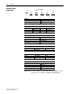
A-2 Specifications Specifications Common to All SCR Bus Supplies Category Input/Output Ratings Control Input Control Output Specification Voltage Tolerance: Frequency Tolerance: Displacement Power Factor: Efficiency: Line Transients: Max. Short Circuit Current Rating: Cooling Blower Power Consumption: Cooling Air: Enable Contactor Coil: Blower Current Consumption: Heat Sink Temperature Sensor: NC Contact Output Rating (Max.): –10% of minimum, +10% of maximum 47…63 Hz. 0.
Specifications Category Environment (continued) Permitted Maximum Capacitance Bus Supply Dimensions A-3 Specification Shock: Vibration: Atmosphere: 15G peak for 11 ms duration (± 1.0 ms) 0.152 mm (0.006 in.) displacement, 1G peak Important: The bus supply must not be installed in an area where the ambient atmosphere contains volatile or corrosive gas, vapors or dust.
A-4 Specifications Figure A.2 400A Unit Bus Bar Customer Connection Point Dimensions/Locations 233 (9.2) 15 (0.6) 58 (2.3) L3 L2 L1 DC- DC+ 144 (5.7) 58 (2.3) 77.5 (3.05) 190 (7.5) M8 PE PE 50 (1.97) 243 (9.6) Dimensions are in millimeters and (inches).
Specifications Figure A.3 A-5 600A Unit Bus Bar Customer Connection Point Dimensions/Locations 243 (9.6) 100 (3.94) DC- DC+ 160 (7.5) F1 F2 F3 L1 L2 L3 F6-F8 F12 F5 F4 40 (1.57) 70 (2.56) 40 (1.57) 68 (2.7) 147 (5.8) 70 (2.56) PE PE 50 (1.97) 243 (9.6) 304 (12) Dimensions are in millimeters and (inches).
A-6 Specifications Figure A.4 1000A Unit Bus Bar Customer Connection Point Dimensions/Locations 100 (3.94) 249 (9.8) 61.5 (2.4) DC+ DC- 40 (1.57) L3 L2 L1 70 (2.56) 40 (1.57) 57 (2.24) 157.5 (6.2) 70 (2.56) PE PE 50 (1.97) 249 (9.8) Dimensions are in millimeters and (inches). Front View PowerFlex SCR Bus Supply User Manual Publication 20S-UM001G-EN-P 338.5 (13.
Specifications Accessories A-7 Line Reactors A minimum reactance is required to limit peak currents in the AC line and the bridge circuit. This can be accomplished either by a matched supply transformer or by adding line reactors to ensure the requested minimum voltage drop over the total line impedance. The preferred method is to install a minimum 3% line reactor, which will also reduce line harmonics. Use Table A.A through Table A.
A-8 Specifications Table A.B 480V, 60Hz Line Reactor Selection Drives Ranges of Drives DC Amp Sum for Typical Supply Transformers (1) Sum of DC Amps 630 kVA 5% 51 µH 800 kVA 5% 41 µH 1000 kVA 1250 kVA 1600 kVA 2500 kVA 3000 kVA Induct. Catalog No. 5.5% 6% 6% 6.5% 6.
Specifications A-9 Table A.C 600V, 60Hz Line Reactor Selection Drives Ranges of Drives DC Amp Sum for Typical Supply Transformers (1) Sum of DC Amps 630 kVA 5% 78 µH 800 kVA 5% 62 µH 1000 kVA 1250 kVA 1600 kVA 2500 kVA 3000 kVA Induct. Catalog No. 5.5% 6% 6% 6.5% 6.
A-10 Specifications Table A.D 690V, 50Hz Line Reactor Selection Drives Ranges of Drives DC Amp Sum for Typical Supply Transformers (1) Sum of DC Amps 630 kVA 5% 123 µH 800 kVA 5% 95 µH 1000 kVA 1250 kVA 1600 kVA 2500 kVA 3000 kVA Induct. Catalog No. 5.5% 6% 6% 6.5% 6.
Specifications A-11 HF Filter It is recommended to install one HF filter (Catalog No. 20S-RFC) in every system. When this filter is used, the HF emission limits for class A, group 2* (EN 55011) in the 2nd environment (industrial supply network) according to the product standard EN 61800-3 are met and the Bus Supply fulfills CE conformity. The HF filter is connected in front of the AC line reactor between the three AC line input phases and the protection earth conductor PE (Figure A.5). Figure A.
A-12 Specifications Solid Ground Systems Using the hole location dimensions from Figure A.6, install the HF filter using the four (4) M4 x 20 screws through the four holes in the plastic body of the HF filter (Figure A.7). Then install the three (3) M4 x 8 screws through the PE grounding plate. Do NOT use the nylon standoffs. Figure A.
Specifications A-13 This page intentionally left blank.
A-14 Specifications Spare Parts 400A SCR Bus Supply Important: SCR Bus Supplies are NOT designed to be field repaired, but can be field maintained. Figure A.
Specifications A-15 Table A.E 400A Unit Spare Part Numbers/Descriptions Item 3 4 6 7 Availability (1) — Yes — Yes Description 400A SCR Set Fan Assembly (2) 400A and 600A MOV Assembly 40A Fuse (Precharge fuses F6…F8) (3) 8 Yes 400A, 700V Fuse (AC fuses F1…F3) Torque to 13 N•m (115 lb•in). 9 Yes 450A, 700V Fuse (DC fuses F4 and F5) Torque to 13 N•m (115 lb•in).
A-16 Specifications 600A SCR Bus Supply Important: SCR Bus Supplies are NOT designed to be field repaired, but can be field maintained. Figure A.
Specifications A-17 Table A.F 600A Unit Spare Part Numbers/Descriptions Item 2 4 6 7 Availability (1) — Yes — Yes 10 Yes 11 Yes 12 13 15 18 19 22 24 25 27 29 31 32 Yes — — Yes — — — — — — — — 35 38 Yes Yes Description 600A SCR Set Fan Assembly (2) 400A and 600A MOV Assembly 40A Fuse (Precharge fuses F6…F8) (3) Rockwell Catalog No. SK-20S-MCC312-18IO1 SK-D9-FAN2 SK-20S-VBKSDK041 SK-20S-F070B040S or Westcode Type F070B040S or Ferraz Shawmut Type 6.921CPgRC14.
A-18 Specifications 1000A SCR Bus Supply Important: SCR Bus Supplies are NOT designed to be field repaired, but can be field maintained. Figure A.
Specifications A-19 Table A.G 1000A Unit Spare Part Numbers/Descriptions Item 1 4 5 7 Availability (1) — Yes — Yes Description 1000A SCR Set Fan Assembly (2) 1000A MOV Assembly 40A Fuse (Precharge fuses F7…F11) (3) 11 Yes 1000A, 700V Fuse (AC fuses F1…F6) Torque to 25 N•m (221 lb•in).
A-20 Specifications Notes: PowerFlex SCR Bus Supply User Manual Publication 20S-UM001G-EN-P
Appendix B History of Changes Topic 20S-UM001F-EN-P, March 2011 Page B-1 This appendix summarizes the revisions to this manual. Reference this appendix if you need information to determine what changes have been made across multiple revisions. This may be especially useful if you are deciding to upgrade your hardware or software based on information added with previous revisions of this manual. 20S-UM001F-EN-P, March 2011 Change Reformatted document from half size (5.5 x 8.5 in.) to full size (8.
B-2 History of Changes Notes: PowerFlex SCR Bus Supply User Manual Publication 20S-UM001G-EN-P
Index A F AC input HF filter, A-11 line reactors, A-7 to A-10 voltages, A-1 filter HF, A-11 RFI, 1-5 AC supply grounding, 1-5 non-grounded, 1-4 source considerations, 1-4 unbalanced, 1-4 fusing 1000A unit, 1-7, A-19 400A unit, 1-7, A-15 600A unit, 1-7, A-17 ambient operating temperature, 1-3 B before applying power, 2-2 C cable trays, 1-7 firmware release, P-2 G general precautions, P-3 grounding bus, 1-5 conductor, 1-5 general, 1-5 impedance, 1-5 safety, PE, 1-5 catalog number explanation, P-4 C
Index-2 operating temperature, 1-3 setting jumpers, 1-12 short circuit protection, 1-7 P parallel connection of slave units (1000A only), 1-15 slave unit (1000A only) parallel connection, 1-15 spare parts, A-14 to A-19 PE ground, 1-5 specifications, A-1 to A-3 power wiring, 1-7 start-up checklist, 2-2 powering up bus supply, 2-2 static discharge, ESD, P-3 precautions, general, P-3 status indicators, 2-4 supply source for AC, 1-4 R related documentation, P-1 removing cover, 1-2 replacing fuses 1
Rockwell Automation Support Rockwell Automation provides technical information on the Web to assist you in using its products. At http://www.rockwellautomation.com/support/, you can find technical manuals, a knowledge base of FAQs, technical and application notes, sample code and links to software service packs, and a MySupport feature that you can customize to make the best use of these tools.