
Manual

4 Rockwell Automation Publication 750-IN020C-EN-P - May 2012
PowerFlex 755 IP00, NEMA/UL Open Type Drive
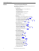
Overview
Selecting and Integrating an IP00 System
The following steps will guide you in planning and installing a PowerFlex 755
IP00, NEMA/UL Open Type drive.
1. Considerations
❏ Drive size (Hp & V AC), required accessories/options (HIM, comms, etc.)
❏ Ingress protection of system
❏ Mounting orientation of drive
❏ Cooling method, venting orientation, alignment of venting
❏ Control pod mounting location
❏ Cabling entry/exit scheme and cable routing provisions
❏ Roll-out cart required
❏ Personnel safety and necessary tooling
2. Selection
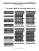
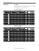
❏ Select and purchase enclosure with sub-panel and ingress accessories (page 16)
❏ Select and purchase drive and corresponding drive options (see 750-TD001
)
❏ Select and purchase pod and corresponding cables (page 10
or page 14)
❏ Select and purchase field termination kits (page 10
or page 14)
❏ Select and purchase appropriate mounting kits (drive mounting & floor - page 10
or page 14)
❏ Select and purchase door fans (pages 20
…21)
❏ Select and purchase necessary wire and cabling (pages 45
& 59)
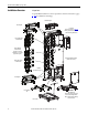
3. Prepare the Enclosure
❏ Create ventilation openings, mount door fans (pages 17…21)
❏ Provisions for accessories (HIM cradle, etc. - see 750-TD001
)
❏ Fabricate and mount inlet and outlet plenums (pages 17
…19)
❏ Drill sub-panel(s) (page 39
& page 40)
❏ Mount field termination kit, mounting brackets, and floor kit (page 39
& page 40)
❏ Mounting of customer specified accessories
❏ Remote mounting of control pod (if specified - see 750-IN015
)
❏ Mount sub-panel(s)
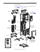
4. Power and Ground Wiring
❏ Ensure proper grounding (page 45)
❏ Position & secure movable L-brackets (page 49
)
❏ Properly terminate power cables (page 48
)
❏ Attach power cabling (page 48
)
5. Roll-in and Secure the Drive Unit
❏ Raise drive unit to vertical orientation (page 37)
❏ Position roll-out cart (see 750-IN001
)
❏ Lift drive unit onto cart (see 750-IN001
)
❏ Roll drive unit into cabinet and secure (see 750-IN001
)
6. Control Wiring
❏ Mount control pod into drive (if specified - page 42)
❏ Verify control transformer voltage (page 41
)
❏ Ensure proper cable routing (page 58
)
❏ Attach pod power and fiber optic cables (page 58
)
❏ Install real time clock battery and HIM cable (page 60
)
❏ Install remaining control wiring (pages 59
…66)
❏ Verify correct torque on all fasteners and connectors
7. Commission the System