
Manual

2 Rockwell Automation Publication 750-IN020C-EN-P - May 2012
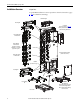
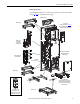
PowerFlex 755 IP00, NEMA/UL Open Type Drive
Additional Resources
For additional PowerFlex 750-Series drive information, refer to the following
publications online at: www.rockwellautomation.com/literature
.
To order paper copies of technical documentation, contact your local
Allen-Bradley distributor or Rockwell Automation sales representative.
For Drives Technical Support see www.ab.com/support/abdrives
.
General Precautions
Qualified Personnel
Personal Safety
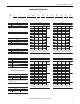
Title Publication
PowerFlex 750-Series Installation Instructions 750-IN001
PowerFlex 750-Series Programming Manual 750-PM001
PowerFlex 750-Series Hardware Service Manual 750-TG001
PowerFlex 750-Series Technical Data 750-TD001
Wiring and Grounding Guidelines for Pulse Width Modulated (PWM) AC Drives DRIVES-IN001
Common Bus Guidelines DRIVES-AT002
Safety Guidelines for the Application, Installation & Maintenance of Solid State Control SGI-1.1
Guarding Against Electrostatic Damage 8000-4.5.2
ATTENTION: Only qualified personnel familiar with adjustable frequency AC
drives and associated machinery should plan or implement the installation,
start-up and subsequent maintenance of the system. Failure to comply may
result in personal injury and/or equipment damage.
ATTENTION: To avoid an electric shock hazard, ensure that all power to the
drive has been removed before proceeding. In addition, before servicing, verify
that the voltage on the bus capacitors has discharged. Measure the DC bus
voltage on Frame 8 drives at the DC+ and DC- TESTPOINT sockets on the front of
the power module (see page 47
). The voltage must be zero.
ATTENTION: Hazard of personal injury or equipment damage exists when
using bipolar input sources. Noise and drift in sensitive input circuits can cause
unpredictable changes in motor speed and direction. Use speed command
parameters to help reduce input source sensitivity.
ATTENTION: Risk of injury or equipment damage exists. DPI or SCANport host
products must not be directly connected together via 1202 cables.
Unpredictable behavior can result if two or more devices are connected in this
manner.
ATTENTION: The drive start/stop/enable control circuitry includes solid state
components. If hazards due to accidental contact with moving machinery or
unintentional flow of liquid, gas or solids exists, an additional hardwired stop
circuit may be required to remove the AC line to the drive. An auxiliary braking
method may be required.