Installation Instructions PowerFlex 755 IP00, NEMA/UL Open Type Drive Frames 8…10 200…1500 kW (250…2000 Hp) This document provides instructions for the installation of an IP00, Open Type PowerFlex 755 drive (Frames 8…10) in a user supplied enclosure. The information provided in this publication supplements the PowerFlex 750Series Installation Instructions (publication 750-IN001) and is intended for qualified drive service personnel only.
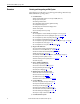
PowerFlex 755 IP00, NEMA/UL Open Type Drive Additional Resources For additional PowerFlex 750-Series drive information, refer to the following publications online at: www.rockwellautomation.com/literature.
PowerFlex 755 IP00, NEMA/UL Open Type Drive Personal Safety (continued) ATTENTION: Hazard of personal injury or equipment damage due to unexpected machine operation exists if the drive is configured to automatically issue a Start or Run command. Do not use these functions without considering applicable local, national and international codes, standards, regulations or industry guidelines.
PowerFlex 755 IP00, NEMA/UL Open Type Drive Overview Selecting and Integrating an IP00 System The following steps will guide you in planning and installing a PowerFlex 755 IP00, NEMA/UL Open Type drive. 1. Considerations ❏ ❏ ❏ ❏ ❏ ❏ ❏ ❏ Drive size (Hp & V AC), required accessories/options (HIM, comms, etc.
PowerFlex 755 IP00, NEMA/UL Open Type Drive Catalog Number Explanation Position 1…3 4 5 6 7 8…10 11 12 13 14 15 16 17 18 20G 1 1 T D 485 A N 0 N N N N N a b c d e f1…f2 g h a f1 f3 Drive ND Rating ND Rating Code Type 20G PowerFlex 755 400V AC / 540V DC, 50 Hz Input b Future Use c Input Type Code 1 4 Description AC Input w/Precharge DC Input w/Precharge d Enclosure Code Description T IP00, UL Open Type without Control POD Amps C460 460 250 C540 540
PowerFlex 755 IP00, NEMA/UL Open Type Drive Installation Overview AC Input Drives A typical IP00 installation for an AC input drive is shown below. Refer to pages 8…10 for available kits and ratings. Outlet Ducting Kit Mounting Kit Control Pod For drive mounting, see page 42. Refer to publication 750-IN015 for remote mounting information. PE PE R/L1 PE Converter (AC Input) Termination Kit PE S/L2 Power 755 T/L3 Inverter (DC Bus) Termination Kit Optional for a Frame 8 equivalent.
PowerFlex 755 IP00, NEMA/UL Open Type Drive Common DC Input Drives A typical IP00 installation for a common DC input drive is shown below. Refer to pages 12…14 for available kits and ratings. Outlet Ducting Kit Mounting Kit Control Pod For drive mounting, see page 42. Refer to publication 750-IN015 for remote mounting information.
PowerFlex 755 IP00, NEMA/UL Open Type Drive Drive Ratings AC Input Drives The following tables provide rating and selection information for the PowerFlex 755 IP00 NEMA/UL Open Type AC input drives. 380…480V AC, Three-Phase, 50 Hz Input Three-Phase, 0…400 Hz Output Light Duty Normal Duty Output Amps Heavy Duty Output Amps Input Voltage Range kW Output Amps Input Amps Cont. 1 Min. 3 Sec.
PowerFlex 755 IP00, NEMA/UL Open Type Drive 600V AC, Three-Phase, 60 Hz Input Three-Phase, 0…400 Hz Output Light Duty Normal Duty Output Amps Heavy Duty Output Amps Input Voltage Range Hp Output Amps Input Amps Cont. 1 Min. 3 Sec.
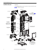
PowerFlex 755 IP00, NEMA/UL Open Type Drive AC Input Drive Installation Kits The following kits are available to assist you with installation of drive components in your enclosure. Note that certain kits are required for proper installation and for UL certification. No.
PowerFlex 755 IP00, NEMA/UL Open Type Drive ➏ Frame 8 ➍ ➐ ➊ PE PE ➌ ➑ ➋ PE PE Power ➍ 755 ➎ ➏ Frame 9 ➍ ➒ ➊ ➓ ➌ ➋ ➍ ➏ ➎ Frame 10 ➏ ➍ ➊ ➌ ➋ ➍ ➎ Rockwell Automation Publication 750-IN020C-EN-P - May 2012 11
PowerFlex 755 IP00, NEMA/UL Open Type Drive Drive Ratings Common DC Input Drives The following tables provide rating and selection information for the common DC input PowerFlex 755 IP00 NEMA/UL Open Type drives. 540V DC, 50 Hz Input Three-Phase, 0…400 Hz Output Light Duty Normal Duty Output Amps Heavy Duty Output Amps Input Voltage Range kW Output Amps Input Amps Cont. 1 Min. 3 Sec.
PowerFlex 755 IP00, NEMA/UL Open Type Drive 810V DC, 60 Hz Input Three-Phase, 0…400 Hz Output Light Duty Normal Duty Output Amps Heavy Duty Output Amps Input Voltage Range Hp Output Amps Input Amps Cont. 1 Min. 3 Sec.
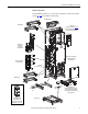
PowerFlex 755 IP00, NEMA/UL Open Type Drive Common DC Input Drive Installation Kits The following kits are available to assist you with installation of drive components in your enclosure. Note that certain kits are required for proper installation and for UL certification. Frame 8 Equivalent Frame 9 Equivalent No.
PowerFlex 755 IP00, NEMA/UL Open Type Drive ➎ Not Shown Frame 8 ➌ ➏ ➊ ➐ Power ➋ 755 ➌ ➑ ➍ ➎ Frame 9 ➌ ➒ ➊ ➋ ➓ ➌ ➍ ➎ Frame 10 ➌ ➊ ➋ ➌ ➍ Rockwell Automation Publication 750-IN020C-EN-P - May 2012 15
PowerFlex 755 IP00, NEMA/UL Open Type Drive Installation Tools Care must be taken to ensure that tools and/or hardware components do not fall into open drive assemblies. Do not energize the drive unless all loose tools and/or hardware components have been removed from the drive assemblies and enclosure. IMPORTANT This list covers the tools needed for drive installation.
PowerFlex 755 IP00, NEMA/UL Open Type Drive In addition, the bus bar must be supported as detailed in the figure below. Power Terminal T45 - M10 x 35 mm SEMS 22.4 N•m (200 lb•in) Bus Bar Drive Support within 305 mm (12.0 in.) Environmental Requirements The drive shall be mounted in an enclosure with 40 °C ambient external to the enclosure and surrounding airflow as described on pages 17…20. Refer to the PowerFlex 750-Series Technical Data, publication 750-TD001 for detailed specifications and ratings.
PowerFlex 755 IP00, NEMA/UL Open Type Drive Figure 1 - Dual Airflow System Ventilation Requirements No. ➍ ➊ ➋ Free Area Description 2 2 780 cm (120.9 in. ) Enclosure Cooling (1) ➋ Enclosure Fans ➌ See Important statement below ➍ 2 2 811.6 cm (125.8 in. ) Drive Power Cooling (1) Enclosure fans are required and must meet or exceed the performance shown in Figure 5. In addition, the fans should be mounted as high as possible on the door and aligned with the front of the drive assembly.
PowerFlex 755 IP00, NEMA/UL Open Type Drive Figure 3 - Outlet Ducting Kit (20-750-DUCT2-F8) Details Outlet Ducting kit attaches to top mounting bracket and should be installed before the drive unit is rolled-in. User supplied ducting is mounted to enclosure top and matches up with the ducting kit. Use M6 screws of suitable length to attach duct to adapter. PE PE T40 - M8 11.3 N•m (100 lb•in) Figure 4 - Outlet Ducting Kit (20-750-DUCT2-F8) Dimensions M6 Hole - 14 places Torque 5.1 N•m (45 lb•in) 181.
PowerFlex 755 IP00, NEMA/UL Open Type Drive Enclosure Fans Enclosure fans are required and must meet or exceed the performance shown in Figure 5 for two fans operating at 10.76 CMM (380 CFM) each with 1.27 mm (0.05 in.) H2O static pressure. Figure 5 - Fan Performance (per bay) Flowrate (CMM) 0.00 2.55 5.09 7.64 10.19 12.75 25.0 0.98 60 Hz 20.0 0.78 15.0 0.59 10.0 0.39 5.0 Static Pressure (InAq) Static Pressure (mmAq) 50 Hz 0.20 0.
PowerFlex 755 IP00, NEMA/UL Open Type Drive ATTENTION: To avoid an electric shock hazard when servicing the drive, a means for Lockout/Tagout of an external 120/240V power source must be provided. Locking and tagging the common bus precharge disconnect switch alone does not provide sufficient protection when servicing the drive. Figure 6 - Terminal Block for Enclosure Fans - TB2 AC Input Drive Common DC Input Drive = 1 2 3 4 1 2 3 4 5 6 TB2 TB2 Flat 0.5 N•m (4.5 lb•in) Flat 0.5 N•m (4.
PowerFlex 755 IP00, NEMA/UL Open Type Drive Drive Grounding A PE termination point is supplied with the Inverter (AC Output) and Converter (AC Input) termination kits shown on page 6 and page 7. Mounting/ drilling recommendations are provided on page 39 and page 40. The PE termination point must be connected to an external ground at the installation site according to local regulations. Connect a grounding cable from the drive assembly to a grounding location shown in Figure 7.
PowerFlex 755 IP00, NEMA/UL Open Type Drive CE Conformity IMPORTANT Additional palm safe shield(s) are required for operator safety and CE conformance. Compliance with the Low Voltage Directive and Electromagnetic Compatibility Directive has been demonstrated using harmonized European Norm (EN) standards published in the Official Journal of the European Communities. PowerFlex 750-Series drives comply with the EN standards listed below when installed according to this document.
PowerFlex 755 IP00, NEMA/UL Open Type Drive • PowerFlex 750-Series drives generate harmonic current emissions on the AC supply system. When operated on a public low-voltage network it is the responsibility of the installer or user to ensure that applicable requirements of the distribution network operator have been met. Consultation with the network operator and Rockwell Automation may be necessary.
PowerFlex 755 IP00, NEMA/UL Open Type Drive • All control (I/O) and signal wiring to the drive must use cable with a braided shield providing 75% or greater coverage, or the cables must be housed in metal conduit, or equivalent shielding must be provided. When shielded cable is used, only the drive end of the cable shield should be terminated with a low-impedance connection to earth.
PowerFlex 755 IP00, NEMA/UL Open Type Drive Horizontal Mounting Guidelines – Single Drive Unit Only To guard against sub-panel flexing, support pieces should be added to the underside of the panel along each long edge. Figure 8 - Open Style Drive - Horizontal Installation Converter (AC Input) Field Termination Kit Optional Inverter (DC Bus) Field Termination Kit Inverter (AC Output) Field Termination Kit Bottom Inlet Duct Kit Figure 9 - Bottom Inlet Ducting Kit Dimensions M6 x 1 - 18 places 325.00 (12.
PowerFlex 755 IP00, NEMA/UL Open Type Drive Derating Guidelines for Horizontal Mounting - Three-Phase Input/Output, Frame 8 Only Light Duty Normal Duty Heavy Duty 50/60 Hz Input Output 50/60 Hz Input Output 50/60 Hz Input Output Catalog Code Volts Amps Volts Amps Power Volts Amps Volts Amps Power Volts Amps Volts Amps Power 380…400V AC Three-Phase Input, 2 kHZ Carrier Frequency C460 400 450 0-400 439 200 KW 400 450 0-400 439 200 KW 400 321 0-400 313 160 KW C540 400 488 0-400 475 224 KW 400
PowerFlex 755 IP00, NEMA/UL Open Type Drive Dimensions Height without Outlet Ducting Kit 15.9 (0.63) dia. for Lifting, 2 Places 474.3 (18.67) 487.0 (19.17) 375.9 (14.80) Height with Outlet Ducting Kit 13.0 (0.51) 0.3 (0.01) 288.4 (11.36) 195.4 (7.69) 0.4 (0.02) Figure 10 - Drive Unit Dimensions - AC Input Outlet Ducting Kit 2063.7 (81.25) 2012.4 (79.23) 1983.8 (78.10) 1922.6 (75.69) 12.0 (0.47) x 16.0 (0.63) 12.5 (0.49) 1846.6 (72.70) R/L1 1855.8 (61.56) S/L2 60.0 28.6 (2.36) (1.
PowerFlex 755 IP00, NEMA/UL Open Type Drive 474.3 (18.67) 487.0 (19.17) 15.9 (0.63) dia. for Lifting, 2 Places 375.9 (14.80) Height with Outlet Ducting Kit 13.0 (0.51) 0.3 (0.01) 0.4 (0.02) Height without Outlet Ducting Kit 288.4 (11.36) Figure 11 - Drive Unit Dimensions – Common DC Input Outlet Ducting Kit 2063.7 (81.25) 2012.4 (79.23) 1983.8 (78.10) 1922.6 (75.69) 1855.8 (61.56) 1718.6 (67.66) M8 x 1.25 Captive Mounting Fastner, 10 Places +DC 1654.6 (65.14) 1590.6 (62.62) 11.0 (0.
PowerFlex 755 IP00, NEMA/UL Open Type Drive Figure 12 - Overall Dimensions with Mounting and Termination Kits – Frame 8 AC Input 5.0 mm (0.2 in.) - 4 places 11.3 N•m (100 lb•in) 777.9 (30.63) Shown without Outlet Ducting Kit Outlet Ducting Kit 1978.8 (77.91) 1728.6 (68.05) 1619.8 (63.77) 1600.6 (63.02) 2111.8 (83.14) 1472.6 (57.98) 2065.6 (81.32) 2145.0 (84.45) 1228.3 (48.36) 2035.2 (80.13) 1100.0 (43.31) 953.1 (37.52) 788.0 (31.02) 623.0 (24.53) 466.0 (18.35) 236.0 (9.29) 119.2 (4.69) 0.
PowerFlex 755 IP00, NEMA/UL Open Type Drive Figure 13 - Overall Dimensions with Mounting and Termination Kits – Frame 8 Common DC Input 777.9 (30.63) 5.0 mm (0.2 in.) - 4 places 11.3 N•m (100 lb•in) Shown without Outlet Ducting Kit 1978.8 (77.91) 1619.8 (63.77) 2111.8 (83.14) 2035.2 (80.13) 1228.3 (48.36) 1100.0 (43.31) 953.1 (37.52) 788.0 (31.02) 623.0 (24.53) 466.0 (18.35) 236.0 (9.29) 119.2 (4.69) 0.0 (0.00) 0.0 (0.00) 420.5 (16.56) 309.9 (12.20) 93.9 (3.
Rockwell Automation Publication 750-IN020C-EN-P - May 2012 0.0 (0.00) 623.0 (24.53) 788.0 (31.02) 953.1 (37.52) 1100.0 (43.31) 1228.3 (48.36) 1472.6 (57.98) 1600.6 (63.02) 1728.6 (68.05) 420.5 (16.56) 777.9 (30.63) Front View 1577.8 (62.12) 2065.6 (81.32) Dimensions are in millimeters and (inches) 5 mm Hex Key (Allen) 10 places/bay 11.3 N•m (100 lb•in) 2145.0 (84.45) 2111.8 (83.14) 2035.2 (80.13) 5.0 mm (0.2 in.) - 4 places/bay 11.3 N•m (100 lb•in) 157.0 (6.
Rockwell Automation Publication 750-IN020C-EN-P - May 2012 0.0 (0.00) 623.0 (24.53) 788.0 (31.02) 953.1 (37.52) 1100.0 (43.31) 1228.3 (48.36) 420.5 (16.56) 777.9 (30.63) Front View 1577.8 (62.12) Dimensions are in millimeters and (inches) 5 mm Hex Key (Allen) 10 places/bay 11.3 N•m (100 lb•in) 2145.0 (84.45) 2111.8 (83.14) 2035.2 (80.13) 5.0 mm (0.2 in.) - 4 places/bay 11.3 N•m (100 lb•in) Right Side View 309.9 (12.20) 157.0 (6.18) 0.0 (0.00) 119.2 (4.69) 236.2 (9.30) 466.0 (18.
Rockwell Automation Publication 750-IN020C-EN-P - May 2012 0.0 (0.00) 623.0 (24.53) 788.0 (31.02) 953.1 (37.52) 1100.0 (43.31) 1228.3 (48.36) 1472.6 (57.98) 1600.6 (63.02) 1728.6 (68.05) 420.5 (16.56) 777.9 (30.63) 1577.8 (62.12) Front View 2377.9 (93.62) 2065.6 (81.32) 2035.2 (80.13) Dimensions are in millimeters and (inches) 5 mm Hex Key (Allen) 10 places/bay 11.3 N•m (100 lb•in) 2145.0 (84.45) 2111.8 (83.14) 5.0 mm (0.2 in.) - 4 places/bay 11.3 N•m (100 lb•in) 157.0 (6.
Rockwell Automation Publication 750-IN020C-EN-P - May 2012 0.0 (0.00) 623.0 (24.53) 788.0 (31.02) 953.1 (37.52) 1100.0 (43.31) 1228.3 (48.36) 420.5 (16.56) 777.9 (30.63) 1577.8 (62.12) Front View 2377.9 (93.62) 2035.2 (80.13) Dimensions are in millimeters and (inches) 5 mm Hex Key (Allen) 10 places/bay 11.3 N•m (100 lb•in) 2145.0 (84.45) 2111.8 (83.14) 309.9 (12.20) 157.0 (6.18) Right Side View 5.0 mm (0.2 in.) - 4 places/bay 11.3 N•m (100 lb•in) 0.0 (0.00) 119.2 (4.69) 236.2 (9.
PowerFlex 755 IP00, NEMA/UL Open Type Drive Lifting IMPORTANT Consult the enclosure manufacturers documentation for proper enclosure lifting procedures. ATTENTION: To guard against possible personal injury and/or equipment damage… • Inspect all lifting hardware for proper attachment before lifting drive or enclosure. • Do not allow any part of the drive, enclosure or lifting mechanism to make contact with electrically charged conductors or components.
PowerFlex 755 IP00, NEMA/UL Open Type Drive Moving the Drive Assembly to a Vertical Position IMPORTANT When approaching the full upright (vertical) position, be aware of the wheels at the bottom of the drive assembly. Blocking the wheels may be necessary to guard against undesired movement. IMPORTANT Remove shipping brackets prior to installation.
PowerFlex 755 IP00, NEMA/UL Open Type Drive Horizontal Lifting Recommended Lifting Bar (User Supplied) 734.0 (28.90) 12.7 (0.50) Dia. 6 places 659.2 (25.95) 47.6 (1.88) 22.2 (0.88) Recommended Material: AISI C1018 or ASTM A36 Hardness: 66 HRB minimum Minimum Working Load: 318 kg (700 lb) 556.5 (21.91) 69.9 (2.75) Min. 199.6 (7.86) 714.8 (28.14) 1429.4 (56.28) 1585.9 (62.44) 1828.8 (72.00) 12.7 (0.50) Min. Lifting Hardware 416.9 (16.41) 1585.9 (62.44) 1 2 3 Lifting Hole Descriptions 1. 1.
PowerFlex 755 IP00, NEMA/UL Open Type Drive Figure 18 - Frame 8 Drilling Dimensions Drill all holes (qty. 34) to 9.00 (0.354) diameter Fasten kits to the control panel with M8 or 5/16 in. screws. 160.00 (6.299) Ref 1935.28 (76.192) 1821.28 (71.704) 1688.38 (66.472) 1576.27 (62.058) 1462.27 (57.570) 1311.66 (51.640) 1271.66 (50.065) Center Line of Sub Panel 941.66 (37.073) 909.16 (35.794) 771.66 (30.380) 422.42 (16.631) 308.17 (12.133) 192.42 (7.575) 114.00 (4.488) Ref 4 places 78.42 (3.087) 0.00 (0.
PowerFlex 755 IP00, NEMA/UL Open Type Drive Figure 19 - Frame 9 and 10 Drilling Dimensions Drill all holes (qty. 34) to 9.00 (0.354) diameter Fasten kits to the control panel with M8 or 5/16 in. screws. 160.00 (6.299) Ref 1935.28 (76.192) 1821.28 (71.704) 1688.38 (66.472) 1322.77 (52.078) 1311.66 (51.640) 1271.66 (50.065) 1208.77 (47.590) Center Line of Sub Panel 941.66 (37.073) 909.16 (35.794) 771.66 (30.380) 422.42 (16.631) 308.17 (12.133) 192.42 (7.575) 114.00 (4.488) Ref 4 places 78.42 (3.
PowerFlex 755 IP00, NEMA/UL Open Type Drive Selecting/Verifying Control Transformer Voltage The control transformer is located inside the upper right part of the drive assembly and is typically set to match the input line voltage. The control transformer provides the single-phase 240V internal control voltage, power for the drive blower, and the enclosure fans. If the line voltage is different than the voltage class specified on the drive nameplate, it may be necessary to change transformer taps.
PowerFlex 755 IP00, NEMA/UL Open Type Drive Installing the Control Pod in the Drive The following steps will guide you through installation of the Control Pod in the drive. To mount the pod in a remote location up to 23 m (75 ft) from the drive, order the Remote Mount kit (catalog number 20-750-RPD1-F8). 1. Loosen, but do not remove, the bottom two M4 x 12 mm slotted hexalobular screws that secure the control pod cover to the assembly. 2.
PowerFlex 755 IP00, NEMA/UL Open Type Drive 4. Swing the Control Pod into the converter assembly and tighten the captive screws on the back panel. T20 or F - 6.4 mm (0.25 in.) 1.8 N•m (16 lb•in) 5. Insert the two position connector of the single-bay 24V wire harness into terminal P14 on the Fiber Interface Board. 6. Connect one end the fiber-optic cable to P1 (INV1) on the Fiber Interface Board. IMPORTANT Minimum inside bend radius for fiber-optic cable is 50 mm (2 in.).
PowerFlex 755 IP00, NEMA/UL Open Type Drive Fiber Interface Board Connections No. Name Description ➊ Internal 24V Power Connection Connects between P14 and TB1 ➋ Optional 24V Connection User supplied External 24V Power Source (see below) ➌ Inverter Fiber-optic Connection Fiber-optic cable between P1 (fiber-optic transceiver INV1) and Power Layer Interface Board 7.
PowerFlex 755 IP00, NEMA/UL Open Type Drive External Power Supply Connections Power Block AP+ AP– Sh Power Wiring Terminal Name Description AP+ +24 Volt Auxiliary Power AP– Auxiliary Power Common Connections for user supplied power supply: 24V DC ±10%, 5 A, PELV (Protective Extra Low Voltage) or SELV (Safety Extra Low Voltage) Sh Shield Terminating point for wire shields. Grounding Requirements The drive Safety Ground-PE must be connected to system ground.
PowerFlex 755 IP00, NEMA/UL Open Type Drive Wire Recommendations Type Power (1)(2) Standard Description Min. Insulation Rating • Four tinned copper conductors with XLPE insulation. • Copper braid/aluminum foil combination shield and tinned copper drain wire. • PVC jacket. 600V, 75 °C (167 °F) (1) Control and signal wires should be separated from power wires by at least 0.3 meters (1 foot). (2) The use of shielded wire for AC input power may not be necessary but is always recommended.
PowerFlex 755 IP00, NEMA/UL Open Type Drive Power Terminals ATTENTION: To guard against drive damage, Do Not connect power wires directly to the drive power terminals. Power wiring must be connected to bus bars which are fastened to the drive power terminals. Refer to page 16. R/L1 S/L2 Do Not connect field wiring directly to power terminals T/L3 TESTPOINTS DC- DC+ TESTPOINTS DC- M10 x 35 mm SEMS Torque: 22.
PowerFlex 755 IP00, NEMA/UL Open Type Drive Termination Kit Current Rating Current Rating at Specified Drive Input Voltage 380…400V AC 480V AC 600V AC 690V AC 513…540V DC 650V DC 810V DC 932V DC 819A AC 755A AC 514A AC 499A AC 832A AC 800A AC 545A AC 530A AC Termination Kit Converter (AC Input) Inverter (AC Output) Frame Catalog Number 8 20-750-BUS2-F8 8 20-750-BUS3-F8 Inverter (DC Bus) DC Input for Common Bus Precharge Converter (AC Input) 8 8 20-750-BUS4-F8 20-750-BUS5-F8 957A DC 957A DC 882A DC 8
PowerFlex 755 IP00, NEMA/UL Open Type Drive Frame Kit Installation Guidelines 8 Kit Steps Converter AC Input Field Termination 20-750-BUS2-F8 Side Detail Ground Bond Strap (see page 22 for hardware and torque requirements) PE PE 73.50 (2.894) x 12 M10 37.9 N•m (336 lb•in) T40 - M8 9.0 N•m (80 lb•in) 8 Inverter AC Output Field Termination 20-750-BUS3-F8 Movable L-bracket M10 37.9 N•m (336 lb•in) T40 - M8 9.0 N•m (80 lb•in) Side Detail 73.50 (2.
Frame PowerFlex 755 IP00, NEMA/UL Open Type Drive 8 Kit Steps Inverter DC Bus Field Termination 20-750-BUS4-F8 M10 37.9 N•m (336 lb•in) T40 - M8 9.0 N•m (80 lb•in) Side Detail x8 73.50 (2.894) Ground Bond Location (see page 22 for hardware and torque requirements) Movable L-bracket 8 DC Input for Common Bus Precharge Field Termination 20-750-BUS5-F8 1 Side Detail 2 73.50 (2.894) x8 M10 37.9 N•m (336 lb•in) T40 - M8 9.
Frame PowerFlex 755 IP00, NEMA/UL Open Type Drive 8 Kit DC Input for Common Bus Precharge Field Termination (continued) Steps 4 3 Ground Bond Location (see page 22 for hardware and torque requirements) M10 37.
Frame PowerFlex 755 IP00, NEMA/UL Open Type Drive Kit Steps 8 Mounting Floor/Rail … 20-750-MNT3-F8 10 Note: Discard unused spacers Rittal Style Enclosure x2 Hoffman Style Enclosure x2 52 x2 Rockwell Automation Publication 750-IN020C-EN-P - May 2012 The Floor/Rail Kit is supplied with two sets of spacers that are used to adapt the kit to different enclosure types. Refer to the diagram below.
Frame PowerFlex 755 IP00, NEMA/UL Open Type Drive 9 Kit Steps Converter AC Input Field Termination 20-750-BUS2-F9 73.50 (2.894) M10 37.9 N•m (336 lb•in) T40 - M8 9.
Frame PowerFlex 755 IP00, NEMA/UL Open Type Drive 9 Kit Steps Inverter AC Output Field Termination 20-750-BUS3-F9 73.50 (2.894) M10 37.9 N•m (336 lb•in) T40 - M8 9.0 N•m (80 lb•in) 9 Inverter DC Bus Field Termination 20-750-BUS4-F9 (400/480V) 20-750-BUS6-F9 (600/690V) 73.50 (2.894) Ground Bond Location (see page 22 for hardware and torque requirements) M10 37.9 N•m (336 lb•in) T40 - M8 9.
Frame PowerFlex 755 IP00, NEMA/UL Open Type Drive 9 Kit DC Input for Common Bus Precharge Field Termination 20-750-BUS5-F9 Steps M10 37.9 N•m (336 lb•in) T40 - M8 9.0 N•m (80 lb•in) 73.50 (2.
Frame PowerFlex 755 IP00, NEMA/UL Open Type Drive 10 Kit Converter AC Input Field Termination 20-750-BUS2-F10 Steps M10 37.9 N•m (336 lb•in) T40 - M8 9.0 N•m (80 lb•in) 73.50 (2.894) 10 56 Inverter AC Output Field Termination 20-750-BUS3-F10 M10 37.9 N•m (336 lb•in) T40 - M8 9.
Frame PowerFlex 755 IP00, NEMA/UL Open Type Drive 10 Kit Inverter DC Bus Field Termination 20-750-BUS4-F10 (400/480V) 20-750-BUS6-F10 (600/690V) Steps M10 37.9 N•m (336 lb•in) T40 - M8 9.0 N•m (80 lb•in) 73.50 (2.894) Ground Bond Location (see page 22 for hardware and torque requirements) Physical size of fuses are different between 400/480V and 600/690V kits. 10 DC Input for Common Bus Precharge Field Termination 20-750-BUS5-F10 M10 37.9 N•m (336 lb•in) T40 - M8 9.0 N•m (80 lb•in) 73.50 (2.
PowerFlex 755 IP00, NEMA/UL Open Type Drive Cable Routing Control Pod Cable Routing Supports, clips, and cable ties are provided to help route and secure cabling inside the Control Pod. IMPORTANT • When routing cabling into the control Pod, do not block the cooling fan outlet. • Do not ground shield wires to inner sheet metal bucket supporting option modules. Figure 20 - Frame 8 Control POD Detail ➐ ➎ ➍ ➏ ➌ ➋ ➐ ➊ ➏ ➓ ➒ ➑ No.
PowerFlex 755 IP00, NEMA/UL Open Type Drive Important points to remember about I/O wiring: • Always use copper wire. • Wire with an insulation rating of 600V or greater is recommended. • Control and signal wires should be separated from power wires by at least 0.3 meters (1 foot). • For CE compliance, 115 volt digital input wiring must be shielded or must not exceed 30 meters (98 feet) in length.
PowerFlex 755 IP00, NEMA/UL Open Type Drive I/O Terminal Blocks The various I/O terminal blocks are located in the Control Pod. Main Control Board ➊ ➋ ➌ ➍ ➎ ➏ ➐ ➑ Main Control Board Details No. Name Description ➊ HIM Connector DPI Port 1 (HIM Cradle) connection. ➋ Fan Connector Power supply for internal cooling fan. ➌ Battery Receptacle User installed CR1220 lithium coin cell battery provides power to the Real Time Clock (Optional, not supplied).
PowerFlex 755 IP00, NEMA/UL Open Type Drive Terminal Block Specifications Wire Size Range Torque Name Maximum Minimum Maximum Recommended Strip Length Main Control Board - TB1 2.5 mm2 (14 AWG) 0.3 mm2 (28 AWG) 0.25 N•m (2.2 lb•in) 0.2 N•m (1.8 lb•in) 6 mm (0.24 in.) TB1 Terminal Designations Fixed I/O Di 0ac Terminal Name Description Di 0ac Digital Input 0 (120V AC) Connections for AC power supply.
PowerFlex 755 IP00, NEMA/UL Open Type Drive Fiber Interface Board Details No. Name Description ➊ Main Control Board Connector 98 pin main control board interface connection. ➋ P13 Connections for user-supplied 24 volt power. Powers control circuits when main power is removed. ➌ P14 Connections for internal drive-supplied 24 volt power. Connection is factory wired and must not be modified by the user. Powers control circuits when main power is connected.
PowerFlex 755 IP00, NEMA/UL Open Type Drive ATTENTION: Hazard of equipment damage exists if an option module is installed or removed while the drive is powered. To avoid damaging the drive, verify that the voltage on the bus capacitors has discharged completely and all control power is removed before performing any work on the drive. Measure the DC bus voltage at the DC+ and DC- TESTPOINT sockets on the front of the power module (see page 47). The voltage must be zero To install an option module: 1.
PowerFlex 755 IP00, NEMA/UL Open Type Drive I/O Module ATTENTION: Risk of equipment damage exists. Ensure that the correct voltage is applied to the I/O Module digital inputs. Refer to the I/O Module catalog number to determine the voltage rating.
PowerFlex 755 IP00, NEMA/UL Open Type Drive TB1 Terminal Designations Description Sh Shield Terminating point for wire shields when an EMC plate or conduit box is not installed. Ptc– Motor PTC (–) Ptc+ Motor PTC (+) Motor protection device (Positive Temperature Coefficient). 40 on Port X Ao0– Analog Out 0 (–) Ao0+ Analog Out 0 (+) 75 on Port X Ao1– Analog Out 1 (–) Bipolar, ±10V, 11 bit & sign, 2 k ohm minimum load. 4-20 mA, 11 bit & sign, 400 ohm maximum load.
PowerFlex 755 IP00, NEMA/UL Open Type Drive TB2 Terminal Designations (1 Relay and 2 Transistor Outputs: IR2T) Relay Out R0NO R0C Terminal Name Description R0NO Relay 0 N.O. R0C Relay 0 Common R0NC Relay 0 N.C. Relay Normally Open contact output: 240V AC, 24V DC, 2 A max. General Purpose (Inductive) / Resistive Relay Normally Closed contact output: 240V AC, 24V DC, 2 A max.
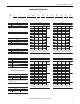
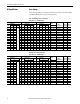
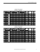
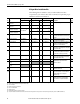
PowerFlex 755 IP00, NEMA/UL Open Type Drive Fuse and Circuit Breaker Ratings The tables on pages 68…74 provide drive ratings (including continuous, 1 minute and 3 second) and recommended AC line input fuse and circuit breaker information. Sizes listed are the recommended sizes based on 40 degree C and the U.S. N.E.C. Other country, state or local codes may require different ratings.
Rockwell Automation Publication 750-IN020C-EN-P - May 2012 8 9 9 9 9 450 kW 400 kW 500 kW 560 kW 630 kW Light 832 Light Normal Heavy 1090 1090 Heavy 1040 1090 Normal 1040 Normal 910 Light Heavy 910 1040 Heavy 880 Heavy Light 750 Light Normal 770 796 Normal 832 Light Heavy 642 750 Normal 750 Light 585 612 Normal Heavy 567 650 Light 540 585 Normal Heavy 540 Heavy 472 Light Heavy 456 540 Normal Heavy Duty 460 385 Cont.
1600 Normal Heavy 1800 10 2150 Light Normal Light 10 1715 10 1590 9 Light Normal 1480 1480 Normal 1465 20G11TC770 20G11TC770 20G11TC567 20G11TC567 20G11TC770 20G11TC770 20G11TC750 20G11TC750 20G11TC650 20G11TC567 20G11TC770 20G11TC650 20G11TC567 Catalog Number 3 3 3 3 2 2 2 2 2 2 2 2 2 Quantity 2365 2700 1887 1749 1760 1628 1628 1612 1612 1988 1763 1293 1293 1 min 3240 3240 2058 2385 – 2220 – 2198 – 2385 2220 1872 – 3 sec 2117 1773 16
Rockwell Automation Publication 750-IN020C-EN-P - May 2012 9 9 9 9 700 Hp 750 Hp 800 Hp 900 Hp Light Normal Normal Heavy 1045 1045 Heavy 960 Light Normal 960 1045 Light 960 Heavy 800 800 Heavy Heavy 795 710 800 Normal 740 Normal Light 765 710 617 Light Normal Heavy 617 710 Light 545 590 Normal Heavy 545 Heavy Light 485 545 Normal 485 Heavy 454 Light Heavy 485 Normal 414 Heavy Duty 430 370 Cont.
10 1730 10 2070 1650 Hp 1750 Hp Normal Heavy Light 20G11TD740 20G11TD740 20G11TD545 20G11TD545 20G11TD740 20G11TD740 20G11TD710 20G11TD545 20G11TD710 20G11TD617 20G11TD740 20G11TD617 20G11TD545 Catalog Number 3 3 3 3 2 2 2 2 2 2 2 2 2 Quantity 2277 2595 1821 1678 1694 1562 1562 1905 1502 1502 1703 1249 1249 1 min 3114 3114 1986 2288 – 2130 – 2288 2048 – 2130 1728 – 3 sec 1953 1633 1562 1439 1453 1340 1340 1199 1288 1288 1071 1071 1071
Rockwell Automation Publication 750-IN020C-EN-P - May 2012 8 9 9 9 9 9 550 Hp 500 Hp 600 Hp 700 Hp 750 Hp 800 Hp Normal 510 Light Heavy Normal Light 760 760 760 Heavy 595 700 Normal 630 Normal Heavy 595 630 Heavy Heavy 595 510 Light Normal 460 545 Light 510 Heavy Light 425 460 Normal 435 395 Light Normal Heavy 395 435 Light 395 Heavy 355 Normal Heavy 355 329 Light Normal 355 Heavy 295 Heavy Duty 295 272 Cont.
10 1190 10 1430 1400 Hp Normal Heavy Light Normal 20G11TE510 20G11TE510 20G11TE395 20G11TE395 20G11TE980 20G11TE395 20G11TE460 20G11TE980 20G11TE435 20G11TE460 20G11TE395 20G11TE435 20G11TE980 Catalog Number 3 3 3 3 2 3 2 2 2 2 2 2 2 Quantity 1573 1785 1342 1221 1150 1380 1078 1078 990 990 919 908 1223 1 min 2145 2145 1464 1665 – 1665 – 1470 – 1368 – 1260 1470 3 sec 1350 1123 1151 1048 986 868 925 925 849 849 788 779 769 Amps 900 9
Rockwell Automation Publication 750-IN020C-EN-P - May 2012 8 8 8 9 9 9 9 9 9 450 kW 500 kW 530 kW 450 kW 500 kW 560 kW 630 kW 710 kW 750 kW 330 370 Normal Light 710 765 Normal 710 Light 650 Heavy Normal 750 Heavy 650 Normal 650 Heavy 590 Heavy Heavy 590 500 460 Light Normal 530 500 Normal Light 500 460 Heavy 413 Light Normal 415 460 Light 410 Heavy Normal Heavy 370 375 Light Normal Light 370 330 Heavy Heavy 308 Normal 265 Heavy D
1020 10 1400 1400 kW Normal Heavy Light Normal Light 20G11TF500 20G11TF500 20G11TF370 20G11TF370 20G11TF460 20G11TF370 20G11TF460 20G11TF960 20G11TF415 20G11TF370 20G11TF460 20G11TF960 Catalog Number 3 3 3 3 2 3 2 2 2 2 2 2 Quantity 1540 1740 1265 1144 1122 1298 1056 1056 946 869 875 1193 1 min 2100 2100 1380 1560 – 1560 – 1440 – – 1350 1440 3 sec 1319 1093 1083 980 961 815 904 904 810 744 749 749 Amps 900 900 900 900 900 900 900
Rockwell Automation Support Rockwell Automation provides technical information on the Web to assist you in using its products. At http://www.rockwellautomation.com/support/, you can find technical manuals, a knowledge base of FAQs, technical and application notes, sample code and links to software service packs, and a MySupport feature that you can customize to make the best use of these tools.