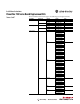
Installation Instructions PowerFlex 750-Series Board Replacement Kits Frames 6 and 7 These installation instructions support the following board replacement kits. Board Type AC Precharge Drive Frame 6 7 DC Precharge 6 7 Power Interface 6 Voltage 400/480 600/690 400/480 600/690 400/480 600/690 400/480 600/690 400/480 600 690 7 400/480 600 690 Cat. No.
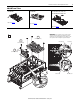
PowerFlex 750-Series Board Replacement Kits 400/480V Frame 6 Drives AC Precharge Board SK-R9-PCG1-DF6 DC Precharge Board SK-R9-PCG2-DF6 Step 2: See page 3. Step 2: See page 3. Power Interface Board 400V: SK-R9-PINT-CF6A, -CF6B, -CF6C, -CF6D 480V: SK-R9-PINT-DF6A, -DF6B, -DF6C, -DF6D Step 2: See page 4. 1 T20 2.6 N•m (23 lb•in) M6 x 1.0 5.2 N•m (46 lb•in) IMPORTANT: Power Jumpers may need to be removed during this procedure.
PowerFlex 750-Series Board Replacement Kits 400/480V Frame 6 Drives – AC and DC Precharge Boards SK-R9-PCG1-DF6, SK-R9-PCG2-DF6 2 T20 2.6 N•m (23 lb•in) Control Cable M6 x 1.0 5.2 N•m (46 lb•in) IMPORTANT: Note the position of the PE-A jumper wire before disassembly (AC Precharge Boards only). Use the same position when installing the replacement board. Positions are identified in Step 1 on page 2.
PowerFlex 750-Series Board Replacement Kits 400/480V Frame 6 Drives – Power Interface Board 400V: SK-R9-PINT1-CF6A, -CF6B, -CF6C, -CF6D / 480V: SK-R9PINT1-DF6A,-DF6B, -DF6C, -DF6D ATTENTION: Replacing the Power Interface Board will result in the loss of drive data including elapsed power consumption, elapsed run times, and preventive maintenance data. 2 2.6 N•m (23 lb•in) 1.3 N•m (12 lb•in) T20 T20 M6 x 1.0 2.6 N•m (23 lb•in) IMPORTANT: Note the position of the PE-B jumper wire before disassembly.
PowerFlex 750-Series Board Replacement Kits 600/690V Frame 6 Drives AC Precharge Board SK-R9-PCG1-FF6 DC Precharge Board SK-R9-PCG2-FF6 Step 2: See page 6. Step 2: See page 6. Power Interface Boards 600V: SK-R9-PINT1-EF6A, B, C, D, E, F, G H, J, K, M, N, P 690V: SK-R9-PINT1-FF6A, B, C, D, E, F, G H, J, K, L, M, N Step 2: See page 7. 1 T20 M6 x 1.0 5.2 N•m (46 lb•in) 2.6 N•m (23 lb•in) IMPORTANT: Power Jumpers may need to be removed during this procedure.
PowerFlex 750-Series Board Replacement Kits 600/690V Frame 6 Drives – AC and DC Precharge Boards SK-R9-PCG1-FF6, SK-R9-PCG2-FF6 2 T20 2.6 N•m (23 lb•in) M6 x 1.0 5.2 N•m (46 lb•in) IMPORTANT: Note the position of the PE-A jumper wire before disassembly (AC Precharge Boards only). Use the same position when installing the replacement board. Positions are identified in Step 1 on page 5.
PowerFlex 750-Series Board Replacement Kits 600/690V Frame 6 Drives – Power Interface Boards 600V: SK-R9-PINT1-EF6A, -EF6B, -EF6C, -EF6D, -EF6E, -EF6F, -EF6G, -EF6H, -EF6J, -EF6K, -EF6M, -EF6N, -EF6P 690V: SK-R9-PINT1-FF6A, -FF6B, -FF6C, -FF6D, -FF6E, -FF6F, -FF6G, -FF6H, -FF6J, -FF6K, -FF6L, -FF6M, -FF6N 2 T20 2.
PowerFlex 750-Series Board Replacement Kits 600/690V Frame 6 Drives – Power Interface Boards (Continued) ATTENTION: Replacing the Power Interface Boards will result in the loss of drive data including elapsed power consumption, elapsed run times, and preventive maintenance data. 3 1.3 N•m (12 lb•in) T20 M6 x 1.0 2.6 N•m (23 lb•in) IMPORTANT: Note position of the PE-B jumper wire before disassembly. Use the same position when installing the replacement board.
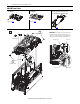
PowerFlex 750-Series Board Replacement Kits 400/480V Frame 7 Drives AC Precharge Board SK-R9-PCG1-DF7 DC Precharge Board SK-R9-PCG2-DF7 Power Interface Board 400V: SK-R9-PINT1-CF7A, -CF7B, -CF7C 480V: SK-R9-PINT1-DF7A, -DF7B, -DF7C Step 2: See page 10. Step 2: See page 10 Step 2: See page 10 1 T30 IMPORTANT: Power Jumpers may need to be removed during this procedure. Note where the PE-A and PE-B jumper wires are terminated before disassembly.
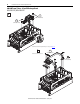
PowerFlex 750-Series Board Replacement Kits 400/480V Frame 7 Drives – AC and DC Precharge Boards SK-R9-PCG1-DF7, SK-R9-PCG2-DF7 2 T30 5.2 N•m (46 lb•in) T20 1.36 N•m (12 lb•in) Power Interface Board replacement go to Step 3 on page 12. 3 Remove bus bars if present. T25 2.6 N•m (23 lb•in) M6 x 1.0 5.
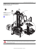
PowerFlex 750-Series Board Replacement Kits 400/480V Frame 7 Drives – AC and DC Precharge Boards (Continued) 4 T30 5.2 N•m (46 lb•in) 5 T20 M6 x 1.0 5.2 N•m (46 lb•in) PE-A 2.6 N•m (23 lb•in) M4 x 7.0 2.6 N•m (23 lb•in) Control Cable Position DC Precharge Boards 600/690V Frame 7 Drives IMPORTANT: Note the position of the PE-A jumper wire before disassembly (AC Precharge Boards only). Use the same position when installing the replacement board. Positions are identified in Step 1 on page 9.
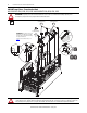
PowerFlex 750-Series Board Replacement Kits 400/480V Frame 7 Drives – Power Interface Board 400V: SK-R9-PINT1-CF7A, -CF7B, -CF7C 480V: SK-R9-PINT1-DF7A, -DF7B, -DF7C ATTENTION: Replacing the Power Interface Board will result in the loss of drive data including elapsed power consumption, elapsed run times, and preventive maintenance data. 3 T20 PE-B 2.6 N•m (23 lb•in) IMPORTANT: Note the position of the PE-B jumper wire before disassembly. Use the same position when installing the replacement board.
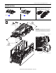
PowerFlex 750-Series Board Replacement Kits 13 600/690V Frame 7 Drives AC Precharge Board SK-R9-PCG1-FF7 DC Precharge Board SK-R9-PCG2-FF7 Steps 2: See page 14. Step 2: See page 14. Power Interface Board 600V: SK-R9-PINT1-EF7A, -EF7B, -EF7C 690V: SK-R9-PINT1-FF7A, -FF7B, -FF7C Step 2: See page 14. IMPORTANT: Power Jumpers may need to be removed during this procedure. Note where the PE-A and PE-B jumper wires are terminated before disassembly.
PowerFlex 750-Series Board Replacement Kits 600/690V Frame 7 Drives (Continued) 2 T30 5.2 N•m (46 lb•in) T20 1.36 N•m (12 lb•in) Precharge Board replacement go to Step 3 on page 15. Power Interface Board replacement go to Step 3 on page 17.
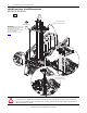
PowerFlex 750-Series Board Replacement Kits 600/690V Frame 7 Drives – AC and DC Precharge Board SK-R9-PCG1-FF7, SK-R9-PCG2-FF7 3 T25 2.6 N•m (23 lb•in) M6 x 1.0 5.2 N•m (46 lb•in) 4 T30 5.
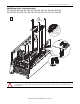
PowerFlex 750-Series Board Replacement Kits 600/690V Frame 7 Drives – AC and DC Precharge Board (Continued) 5 T20 2.6 N•m (23 lb•in) M6 x 1.0 5.2 N•m (46 lb•in) PE-A IMPORTANT: Note the position of the PE-A jumper wire before disassembly (AC Precharge Boards only). Use the same position when installing the replacement board. Positions are identified in Step 1 on page 13. M4 x 7.0 2.
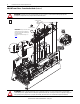
PowerFlex 750-Series Board Replacement Kits 600/690V Frame 7 – Power Interface Board 600V: SK-R9-PINT1-EF7A, -EF7B, -EF7C 690V: SK-R9-PINT1-FF7A, -FF7B, -FF7C ATTENTION: Replacing the Power Interface Board will result in the loss of drive data including elapsed power consumption, elapsed run times, and preventive maintenance data. 3 IMPORTANT: Note the position of the PE-B jumper wire before disassembly. Use the same position when installing the replacement board.
U.S. Allen-Bradley Drives Technical Support - Tel: (1) 262.512.8176, Fax: (1) 262.512.2222, E-mail: support@drives.ra.rockwell.com, Online: www.ab.com/support/abdrives *PN-183692* PN-183692 www.rockwellautomation.com Power, Control and Information Solutions Headquarters Americas: Rockwell Automation, 1201 South Second Street, Milwaukee, WI 53204-2496 USA, Tel: (1) 414.382.2000, Fax: (1) 414.382.