
Instruction Manual

Rockwell Automation Publication 750-IN011E-EN-P - February 2014 5
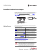
PowerFlex 750-Series Power Jumpers
Jumper Locations and
Settings
The following pages show jumper locations and settings.
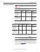
Frame
Voltage
Code
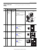
Factory Default Jumper Settings
Power Source TypeCatalog Code “A” Catalog Code “J”
1 C
D
PE-A jumper wire
connected to ground.
PE-B jumper wire
insulated/
disconnected from
ground.
PE-A jumper wire
and PE-B jumper
wire connected to
ground.
Solid Ground
Connect the MOV/Input Filter Cap jumper wire (PE-
A) and the CM Cap jumper wire (PE-B) to ground.
Non-Solid Ground
Insulate the MOV/Input Filter Cap jumper wire (PE-
A) and the CM Cap jumper wire (PE-B) from
ground.
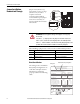
2 C
D
PE-A Installed
PE-B Not Installed
PE-A Installed
PE-B Installed
Solid Ground
Install jumper screws at “PE-A” (MOV/Input Filter
Cap) and “PE-B” (CM Cap).
See page 4
for recommended torque.
Non-Solid Ground
Remove both jumper screws.
3 C
D
E
PE-A Installed
PE-B Not Installed
PE-A Installed
PE-B Installed
Solid Ground
Install jumper screws at “PE-A” (MOV/Input Filter
Cap) and “PE-B” (CM Cap).
See page 4
for recommended torque.
Non-Solid Ground
Remove both jumper screws.
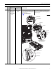
4 C
D
E
PE-A Installed
PE-B Not Installed
PE-A Installed
PE-B Installed
Solid Ground
Install Jumper screws at “PE-A” (MOV/Input Filter
Cap) and “PE-B” (CM Cap).
See page 4
for recommended torque.
Non-Solid Ground
Remove both jumper screws.
PE-A
PE-B
Insulated
Connected
Insulated
Connected
PE-B
PE-A
PE-B
PE-A
PE-B
PE-A