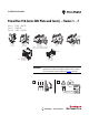
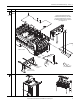
Installation Instructions PowerFlex 750-Series EMC Plate and Core(s) – Frames 1…7 Frames 1…5 (400…480V AC) Frames 3…5 (600V AC) Frames 6…7 (600…690V AC) x2 - Frame 4 x1 - Frame 5 20-750-EMC1-F1 Frame 1 400…480V AC 20-750-EMC1-F2, F3 Frames 2…3 400…480V AC 20-750-EMC3-F3 Frame 3 600V AC 20-750-EMC1-F4, F5 Frames 4…5 * 400…480V AC 20-750-EMC3-F4, F 5 Frames 4…5 600V AC * Frames 6…7, 400…480V drives do not require EMC cores or plates to meet EMC requirements.
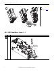
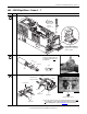
PowerFlex 750-Series EMC Plate and Core(s) – Frames 1…7 4 3 600…690V – see page 5 400…480V AC Input Drives – Frames 1…5 Step 4 Frame Procedure 1 T20 #1 1.
PowerFlex 750-Series EMC Plate and Core(s) – Frames 1…7 Step 4 Frame Procedure 2…5 continued T20 #1 1.8 N•m (16 lb•in) x 2 (Frame 2) x 3 (Frames 3…5) Environments with Vibration Support Plate is recommended to provide core support Frame 2 Shown 5 All Drain wires must be pulled back and wrapped in a 360 degree pattern over the shield/braid surface. Do Not fold the shield back. Shield Drain Ground (PE) Braid Clamp M10 #2 5.
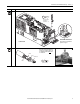
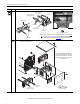
PowerFlex 750-Series EMC Plate and Core(s) – Frames 1…7 Step 6 Frame Procedure 1 Motor Cable (U, V, W) Shielded to PE Stud Input Power (R, S, T) Shielded or Unshielded to PE Stud 1 Loop (each wire) I/O Shields PE T20 or F - 6.4 mm (0.25 in.) 1.8 N•m (16 lb•in) 2…3 Frame 2 Shown Input Power (R, S, T) Shielded or Unshielded Motor Cable (U, V, W) Shielded to PE Stud I/O Signal Shields to PE Stud IP20, NEMA/UL Type 0 PE Flange Mount M4 (7 mm) 1.
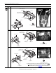
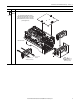
PowerFlex 750-Series EMC Plate and Core(s) – Frames 1…7 600…690V AC Input Drives – Frames 3…7 Step 4 Frame Procedure 3…5 T20 #1 1.8 N•m (16 lb•in) x 2 (Frame 3) x 3 (Frames 4…5) Environments with Vibration Support Plate is recommended to provide core support 5 All Drain wires must be pulled back and wrapped in a 360 degree pattern over the shield/braid surface. Do Not fold the shield back. Shield Drain Ground (PE) Clamp M10 Braid #2 5.
PowerFlex 750-Series EMC Plate and Core(s) – Frames 1…7 Step 6 Frame Procedure 5 Motor Cable (U, V, W) Shielded Input Power (R, S, T) Shielded or Unshielded continued to PE Stud I/O Signal Shields to PE Stud IP20, NEMA/UL Type 0 PE Flange Mount M6 (10 mm) 5.6 N•m (50 lb•in) The motor cable ground wire connects to the motor PE stud in the drive, however it should not go through the core.
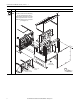
PowerFlex 750-Series EMC Plate and Core(s) – Frames 1…7 Step 6 continued Frame Procedure 6 IP54 The cable shield and drain wires must be terminated at the shield clamp on the conduit plate. The ground wire must be connected to the PE stud in the drive; however, it should not pass through the core. Cabinet not shown x6 x4 Motor Cable (U, V, W) Shielded Input Power (R, S, T) Shielded or Unshielded Rockwell Automation Publication 750-IN006G-MU-P - February 2014 T20 #1 2.6 N•m (23.
PowerFlex 750-Series EMC Plate and Core(s) – Frames 1…7 Step 6 continued Frame Procedure 7 IP00 For use on Frame 7 IP00 drives. After installation, the drive achieves an IP20 rating. x8 The cable shield and drain wires must be terminated at the shield clamp on the conduit plate. The ground wire must be connected to the PE stud in the drive; however, it should not pass through the core. x4 x4 x12 x2 M6 (10 mm) 5.
PowerFlex 750-Series EMC Plate and Core(s) – Frames 1…7 Step 6 Frame Procedure 7 IP54 continued The cable shield and drain wires must be terminated at the shield clamp on the conduit plate. The ground wire must be connected to the PE stud in the drive; however, it should not pass through the core. x4 Cabinet not shown x2 Adheres to cabinet x6 T30 #1 5.2 N•m (46.
Rockwell Automation Support Rockwell Automation provides technical information on the Web to assist you in using its products. At http://www.rockwellautomation.com/support you can find technical and application notes, sample code, and links to software service packs. You can also visit our Support Center at https://rockwellautomation.custhelp.com/ for software updates, support chats and forums, technical information, FAQs, and to sign up for product notification updates.