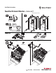
Installation Instructions PowerFlex 750-Series DC Bus Bars – Frame 6 and 7 Frame 6 & 7 (Frame 6 shown) 1 L1 L2 L3 3 I O 2 0V DC+ DC– 0V 90° Frame 6 Kits 20-750-DCBB1-F6 (400/480V) 4 B 20-750-DCBB2-F6 (600/690V) Frame 6 - 600/690V Frame 6 - 400/480V B A M6 x 1.0 5.
PowerFlex 750-Series DC Bus Bars – Frame 6 and 7 Frame 6 - 400/480V Frame 6 - 600/690V 5 T20 1.36 N•m (12 lb•in) M6 x 1.0 5.
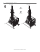
PowerFlex 750-Series DC Bus Bars – Frame 6 and 7 Frame 7 Kits 20-750-DCBB1-F7 (400/480V) 4 5 20-750-DCBB2-F7 (600/690V) Frame 7 - 400/480V Frame 7 - 600/690V Frame 7 - 400/480V Frame 7 - 600/690V PE-B Note where the PE-B jumper wire is terminated. Return the wire to this position in Step 8.
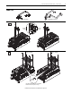
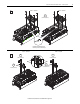
PowerFlex 750-Series DC Bus Bars – Frame 6 and 7 6 T20 Frame 7 - 400/480V Frame 7 - 600/690V 2.6 N•m (23 lb•in) M6 x 1.0 5.2 N•m (46 lb•in) A T30 B 5.2 N•m (46 lb•in) T20 2.6 N•m (23 lb•in) 7 Frame 7 - 400/480V Go to Step 8 Frame 7 - 600/690V M6 x 1.0 5.2 N•m (46 lb•in) T20 2.
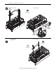
PowerFlex 750-Series DC Bus Bars – Frame 6 and 7 8 Frame 7 - 400/480V Frame 7 - 600/690V T30 5.20 N•m (46 lb•in) PE-B Terminate the PE-B jumper wire in the same position as noted in Step 5. Frame 7 - 400/480V 9 Frame 7 - 600/690V T30 T30 5.2 N•m (46 lb•in) A 5.2 N•m (46 lb•in) B A T25 T25 2.6 N•m (23 lb•in) 2.
U.S. Allen-Bradley Drives Technical Support - Tel: (1) 262.512.8176, Fax: (1) 262.512.2222, E-mail: support@drives.ra.rockwell.com, Online: www.ab.com/support/abdrives *PN-158686* PN-158686 www.rockwellautomation.com Power, Control and Information Solutions Headquarters Americas: Rockwell Automation, 1201 South Second Street, Milwaukee, WI 53204-2496 USA, Tel: (1) 414.382.2000, Fax: (1) 414.382.