
Instruction Manual

Stegmann Feedback Option Board for PowerFlex® 700S Drives 7
Drives with Phase II Control
It is necessary to remove the Phase II control assembly from the drive
before removing the covers.
Important:Before removing connections and wires, mark the connections
and wires to avoid incorrect wiring during assembly.
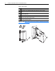
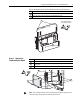
Frame 1-6 Size Drives
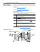
Continue with Remove the Cassette Covers on Drives with Phase II Control
(All Drive Sizes) on page 9
!
ATTENTION: Hazard of permanent eye damage exists when
using optical transmission equipment. This product emits intense
light and invisible radiation. Do not look into fiber-optic ports or
fiber-optic cable connectors.
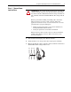
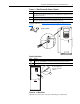
Task Action
Unplug any fiber optic ControlNet and SynchLink cables and I/O cables from the control
assembly.
Disconnect the communications cables at the ends that connect to the main control board.
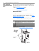
Loosen the screws on the face of the cassette.
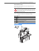
Remove the cassette from the drive.
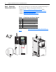
A
B
C
D
BR1
B
R
2
D
C
+
D
C
-
PE
U/T1
V/T2
W/T3
R/L1
L2
B
C
=
D