
Instruction Manual


Stegmann Feedback Option Board for PowerFlex® 700S Drives 17
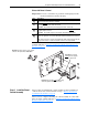
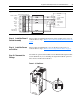
Step 8: Install the Phase II
Control Assembly
The procedure for installing the Phase II control assembly is the reverse of
removal. Refer to Step 3: Remove the Control Assembly from the Drive
on
page 6.
Step 9: Install the Covers
on the Drive
The procedure for installing the covers on all drives is the reverse of
removal. Refer to Step 2: Remove the Cover(s) from the Drive
on page 4.
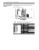
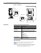
Step 10: Document the
Change
Document the option board installation on the Field Installed Options label.
Use the blank line if you are installing the Stegmann Feedback option in a
drive that was manufactured without it.
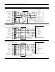
Frame 1 - 6 Size Drives
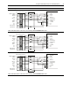
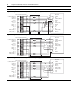
Figure 10 Pre-attached Stegmann shielded twisted-pair cable
Connection Examples
POWER
POWER COMMON
+COS
DATA- (RS 485)
REFSIN
+SIN
DATA+ (RS 485)
REFCOS
1
2
8
6
3
7
5
4
RD
BU
WH
BN
PK
BK
GY
GN
ENCODER
12
11
10
9
8
7
6
5
4
3
2
1
POWER COMMON
POWER
N/C
N/C
+SIN
REFSIN
+COS
REFCOS
SHIELD
SHIELD
DATA+ (RS 485)
DATA- (RS 485)
Hi-Res Feedback Option Board
BU
RD
BN
BK
GY
GN
WH
PK
FIELD INSTALLED OPTIONS
Firmware #: Date
Firmware
20-HIM
28-IO-
20-COMM-
20B_-DB1-
HIM
I/O
COM Module
Internal Dynamic Brake
#: Date