
Instruction Manual


Stegmann Feedback Option Board for PowerFlex® 700S Drives 11
Drives with Phase II Control
Important:Do not use a screwdriver to pry the P1 terminal plug from the
circuit board. This may damage the plug.
Continue with Step 7: Wire the Stegmann Feedback Option Board to an
Encoder on page 12.
Step 6: Install the Phase I
Control Assembly
The procedure for installing the control assembly on drives with Phase I
control is the reverse of removal. Refer to Step 3: Remove the Control
Assembly from the Drive on page 6.
When you have completed installing the control assembly on a drive with
Phase I control, continue with Step 7: Wire the Stegmann Feedback Option
Board to an Encoder on page 12.
Task Description
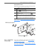
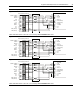
Remove the P1 terminal block from the Stegmann Feedback option board. (It is much
easier to remove before the board is installed.)
Insert the short pins
of the through-board pin connectors (part number 320669-Q04) into
the mating connectors on the main control board.
Important: The end with short pins must plug into the main control board.
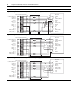
Plug the mating connectors of the Feedback option board onto the long pins
of
through-board pin connectors.
Important: The end with longer pins must plug into the Feedback option board.
Secure the board to the stand-offs using the screws with captive lock washers (supplied
with this kit). Tighten the screws with a Phillips® screwdriver (min/max 6 in.-lb. / 8 in.-lb.).
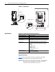
Note: If the option board is not fully seated against the stand-off and is warped, either the
wrong stacker connector is used or the stacker connector is incorrectly installed.
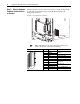
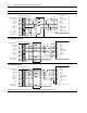
A
B
C
D
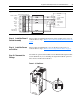
Important: The end with
shorter pins must plug into
the main control board.
D
C
D
D
Important: The end with longer pins must plug
into the Stegmann Feedback option board.
B
Important: For Phase II drives, use the stacker
connectors with part number 320669-Q041.
=