
Instruction Manual

10 Stegmann Feedback Option Board for PowerFlex® 700S Drives
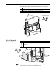
Step 5: Install the
Feedback Option Board
The steps to install the Feedback option board are different for drives with
Phase I control versus drives with Phase II control. Refer to the appropriate
instructions:
• Refer to Drives with Phase I Control
below.
• Refer to Drives with Phase II Control
on page 11.
Drives with Phase I Control
Important:Do not use a screwdriver to pry the P1 terminal plug from the
circuit board. This may damage the plug.
Continue with Step 6: Install the Phase I Control Assembly
.
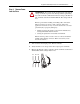
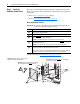
Task Description
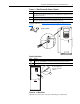
Remove the P1 terminal block from the Feedback option board. (It is much easier to
remove before the board is installed.)
Install and tighten the stand-offs (min/max 7 in.•lb. / 10 in.•lb.).
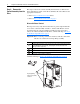
Insert the short pins
of through-board pin connectors (part number 313611) into the
mating connectors on the main control board.
Important: The end with short pins must plug into the main control board.
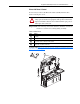
Plug the mating connectors of the Feedback option board onto the long pins
of
through-board pin connectors.
Important: The end with longer pins must plug into the Feedback option board.
Secure board to stand-offs using the screws with the captive lock washers. Tighten the
screws using a Phillips screwdriver (min/max 6 in.•lb. / 8 in.•lb.).
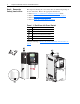
Note: If the option board is not fully seated against the stand-off and is warped, either the
wrong stacker connector is used or the stacker connector is incorrectly installed.
A
B
C
D
E
Important: The end with longer pins must plug
into the Stegmann Feedback option board.
Important: The end with shorter
pins must plug into
the main control board.
D
E
C
B
C
D
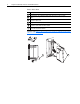
Important: For Phase I drives, use the stacker
connectors with part number 313611.
=