
Installation Instructions Owner's manual

72 Rockwell Automation Publication 20D-IN024C-EN-P - July 2013
PowerFlex 700S Adjustable Frequency AC Drive - Phase II Control
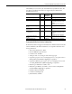
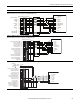
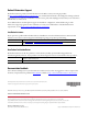
Resolver Feedback Option Terminal Designations
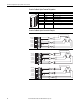
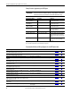
Resolver Feedback Option Connection Examples
Terminal Signal Description
1 COS LOW Negative Cosine signal
2 COS HIGH Positive Cosine signal
3 SIN LOW Negative Sine signal
4 SHIELD Connection point for resolver cable shield
5 SIN HIGH Positive Sine signal
6 REF LOW Negative Reference signal
7 SHIELD Connection point for resolver cable shield
8 REF HIGH Positive Reference signal
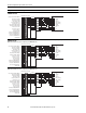
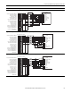
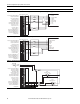
Resolver Interface - Clockwise Rotation = Count Up
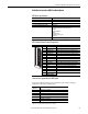
Resolver Interface - Clockwise Rotation = Count Down (Reverse Polarity of Sine or Cosine Signals)
123 45678
REF HIGH 8
SHIELD 7
REF LOW 6
SIN HIGH 5
SHIELD 4
SIN LOW 3
COS HIGH 2
COS LOW 1
REF
+-
SIN COS
+
+
-
-
-
+
-
+
-
+
-
+
-
+
-
+
REF HIGH 8
SHIELD 7
REF LOW 6
SIN HIGH 5
SHIELD 4
SIN LOW 3
COS HIGH 2
COS LOW 1
REF
+-
SIN COS
+
+
-
-
-
+
-
+
-
+
-
+
+
-
-
+
REF HIGH 8
SHIELD 7
REF LOW 6
SIN HIGH 5
SHIELD 4
SIN LOW 3
COS HIGH 2
COS LOW 1
REF
+-
SIN COS
+
+
-
-
-
+
-
+
-
+
+
-
-
+
-
+