
Installation Instructions Owner's manual

48 Rockwell Automation Publication 20D-IN024C-EN-P - July 2013
PowerFlex 700S Adjustable Frequency AC Drive - Phase II Control
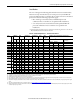
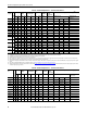
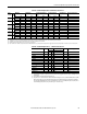
Table 16 - 600 Volt AC Input Frames 1…6 Drive Protection Devices
20DD125 5 100 – 117 97.6 150 250 150 500 375 150 – – – –
– 75 90.1 74.9 125 200 125 350 350 125 – – – –
20DD156 6 125 – 146.5 121.7 200 350 200 600 450 250 – – – –
– 100 131 97.6 175 250 175 500 375 250 – – – –
20DD180 6 150 – 169 140.5 225 400 225 600 500 250 – – – –
– 125 147 121.7 200 350 200 600 450 250 – – – –
20DD248 6 200 232.8 188 300 550 300 700 700 400 – – – –
150 169 140.5 225 400 225 600 500 250 – – – –
(1) Minimum protection device size is the lowest rated device that supplies maximum protection without nuisance tripping.
(2) Maximum protection device size is the highest rated device that supplies drive protection. For US NEC, minimum size is 125% of motor FLA. Ratings shown are maximum.
(3) Circuit Breaker - inverse time breaker. For US NEC, minimum size is 125% of motor FLA. Ratings shown are maximum.
(4) Maximum allowable rating by US NEC. Exact size must be chosen for each installation.
(5) Motor Circuit Protector - instantaneous trip circuit breaker. For US NEC minimum size is 125% of motor/drive FLA. Ratings shown are suggested. Instantaneous trip settings must be set to US NEC code. Not to exceed 1300% FLA.
(6) Bulletin 140M with adjustable current range should have the current trip set to the minimum range that the device will not trip.
(7) Manual Self-Protected (Type E) Combination Motor Controller, UL listed for 208 Wye or Delta, 240 Wye or Delta, 480Y/277 or 600Y/ 347. Not UL listed for use on 480V or 600V Delta/Delta, corner ground, or high-resistance ground systems.
(8) The AIC ratings of the Bulletin 140M Motor Protector Circuit Breakers may vary. See Bulletin 140M Motor Protection Circuit Breakers Application Ratings.
(9) When using a Manual Self-Protected (Type E) Combination Motor Controller, the drive must be installed in a ventilated or non-ventilated enclosure with the minimum volume specified in this column. Application specific thermal considerations may require a larger
enclosure.
Drive Cat.
No.
Frame
HP Rating Input Ratings Dual Element
Time Delay Fuse
Non-Time Delay
Fuse
Circuit
Breaker
(3)
Motor
Circuit
Protector
(5)
140M Motor Starter with Adjustable Current Range
(6)(7)
ND HD Amps kVA Min
(1)
Max
(2)
Min
(3)
Max
(4)
Max
(4)
Max
(6)
Available Cat. No.s
(8)
Minimum Enclosure
Volume (in.
3
)
(9)
Drive
Cat. No.
Frame
HP Rating Input Ratings Dual Element
Time Delay Fuse
Non-Time Delay
Fuse
Circuit
Breaker
(3)
Motor
Circuit
Protector
(5)
140M Motor Starter with Adjustable Current Range
(6)(7)
ND HD Amps kVA Min
(1)
Max
(2)
Min
(3)
Max
(4)
Max
(4)
Max
(6)
Available Cat. No.s
(8)
Minimum Enclosure
Volume (in.
3
)
(9)
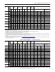
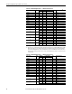
20DE1P7 1 1 0.75 1.3 1.4 2 4 2 6 15 3 M-C2E-B16 – – 7269
20DE2P7 1 2 1.5 2.1 2.1 3 6 3 10 15 3 M-C2E-B25 – – 7269
20DE3P9 1 3 2 3.0 3.1 6 9 6 15 15 7 M-C2E-B40 M-D8E-B40 – 7269
20DE6P1 1 5 3 5.3 5.5 9 12 9 20 20 15 – M-D8E-B63 – 7269
20DE9P0 1 7.5 5 7.8 8.1 10 20 10 35 30 15 – M-D8E-C10 M-F8E-C10 7269
20DE011 1 10 7.5 9.9 10.2 15 25 15 40 40 15 – M-D8E-C10 M-F8E-C10 7269
20DE017 1 15 10 15.4 16.0 20 40 20 60 50 20 – M-D8E-C16 M-F8E-C16 7269
20DE022 2 20 15 20.2 21.0 30 50 30 80 80 30 – – M-F8E-C25 7269
20DE027 2 25 20 24.8 25.7 35 60 35 100 100 50 – – M-F8E-C25 7269
20DE032 3 30 25 29.4 30.5 40 70 40 125 125 50 – – M-F8E-C32 13630
20DE041 3 40 30 37.6 39.1 50 90 50 150 150 100 – – – –
20DE052 3 50 40 47.7 49.6 60 110 60 200 200 100 – – – –
20DE062 4 60 50 58.2 60.5 80 125 80 225 225 100 – – – –
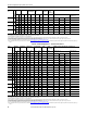
20DE077 5 75 – 72.3 75.1 90 150 90 300 300 100 – – – –
– 60 58.2 60.5 90 125 90 250 250 100 – – – –
20DE099 5 100 – 92.9 96.6 125 200 125 375 375 150 – – – –
– 75 72.3 75.1 100 175 100 300 300 100 – – – –
20DE125 6 125 – 117 121.6 150 250 150 375 375 250 – – – –
– 100 93 96.6 125 200 125 375 375 150 – – – –
20DE144 6 150 – 135 140.5 175 300 175 400 400 250 – – – –
– 125 117 121.6 150 275 150 375 375 250 – – – –
(1) Minimum protection device size is the lowest rated device that supplies maximum protection without nuisance tripping.
(2) Maximum protection device size is the highest rated device that supplies drive protection. For US NEC, minimum size is 125% of motor FLA. Ratings shown are maximum.
(3) Circuit Breaker - inverse time breaker. For US NEC, minimum size is 125% of motor FLA. Ratings shown are maximum.
(4) Maximum allowable rating by US NEC. Exact size must be chosen for each installation.
(5) Motor Circuit Protector - instantaneous trip circuit breaker. For US NEC minimum size is 125% of motor/drive FLA. Ratings shown are suggested. Instantaneous trip settings must be set to US NEC code. Not to exceed 1300% FLA.
(6) Bulletin 140M with adjustable current range should have the current trip set to the minimum range that the device will not trip.
(7) Manual Self-Protected (Type E) Combination Motor Controller, UL listed for 208 Wye or Delta, 240 Wye or Delta, 480Y/277 or 600Y/ 347. Not UL listed for use on 480V or 600V Delta/Delta, corner ground, or high-resistance ground systems.
(8) The AIC ratings of the Bulletin 140M Motor Protector Circuit Breakers may vary. See Bulletin 140M Motor Protection Circuit Breakers Application Ratings.
(9) When using a Manual Self-Protected (Type E) Combination Motor Controller, the drive must be installed in a ventilated or non-ventilated enclosure with the minimum volume specified in this column. Application specific thermal considerations may require a larger
enclosure.