
Installation Instructions Owner's manual

42 Rockwell Automation Publication 20D-IN024C-EN-P - July 2013
PowerFlex 700S Adjustable Frequency AC Drive - Phase II Control
Dynamic Brake Resistor Considerations
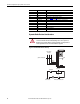
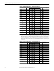
Figure 16 - External Brake Resistor Circuitry
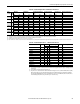
Terminal Description Notes
BR1 DC Brake (+) Dynamic Brake Resistor Connection (+)
BR2 DC Brake (–) Dynamic Brake Resistor Connection (–)
DC+ DC Bus (+) DC Input Power or Dynamic Brake Chopper
DC– DC Bus (–) DC Input Power or Dynamic Brake Chopper
PE PE Ground Refer to Figure 14
on page 40 for location on 3 Frame drives
Motor Ground Refer to Figure 14 on page 40 for location on 3 Frame drives
U U (T1) To motor
V V (T2) To motor
W W (T3) To motor
R R (L1) AC Line Input Power
S S (L2) AC Line Input Power
T T (L3) AC Line Input Power
ATTENTION: The drive does not offer protection for externally mounted brake
resistors. A risk of fire exists if external braking resistors are not protected.
External resistor packages must be self-protected from over temperature or a
circuit equivalent to the one shown below must be supplied.
Power On
R (L1)
S (L2)
T (L3)
Power Source DB Resistor Thermostat
Power Off
M
M
(Input Contactor) M
Three-Phase
AC Input