
Installation Instructions Owner's manual

Rockwell Automation Publication 20D-IN024C-EN-P - July 2013 39
PowerFlex 700S Adjustable Frequency AC Drive - Phase II Control
Power Wire Recommendations
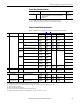
Power Terminal Block Specifications
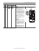
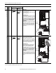
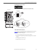
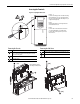
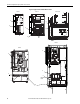
Refer to illustrations on pages 40 and 41 for terminal block locations.
Type Description Min Insulation
Rating
Power
(1)(2)
(1) Control and signal wires should be separated from power wires by at least 0.3 meters (1 foot).
(2) The use of shielded wire for AC input power may not be necessary but is always recommended.
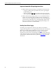
Standard • Four tinned copper conductors with XLPE insulation.
• Copper braid/aluminum foil combination shield and tinned
copper drain wire.
• PVC jacket.
600V,
75 °C (167 °F)
No. Name Frame Description Wire Size Range
(1)
Torque Terminal Bolt Size
(2)
Maximum Minimum Maximum Recommended
1 Power Terminal Block 1 Input power and motor connections 4.0 mm
2
(10 AWG)
0.5 mm
2
(22 AWG)
1.7 N•m
(15 lb•in)
0.8 N•m
(7 lb•in)
—
2 Input power and motor connections 10.0 mm
2
(6 AWG)
0.8 mm
2
(18 AWG)
1.7 N•m
(15 lb•in)
1.4 N•m
(12 lb•in)
—
3 Input power and motor connections 25.0 mm
2
(3 AWG)
2.5 mm
2
(14 AWG)
3.6 N•m
(32 lb•in)
1.8 N•m
(16 lb•in)
—
BR1, BR2 10.0 mm
2
(6 AWG)
0.8 mm
2
(18 AWG)
1.7 N•m
(15 lb•in)
1.4 N•m
(12 lb•in)
—
4 Input power and motor connections 35.0 mm
2
(1/0 AWG)
10 mm
2
(8 AWG)
4.0 N•m
(24 lb•in)
4.0 N•m
(24 lb•in)
—
5
(75 HP)
(3)
R, S, T, BR1, BR2, DC+, DC-, U, V and W 50.0 mm
2
(1/0 AWG)
2.5 mm
2
(14 AWG)
See Note
(4)
See Note
(3)
—
PE 50.0 mm
2
(1/0 AWG)
4.0 mm
2
(12 AWG)
—
5
(100 HP)
(3)
R, S, T, DC+, DC-, U, V and W 70.0 mm
2
(2/0 AWG)
16.0 mm
2
(6 AWG)
—
BR1, BR2 50.0 mm
2
(1/0 AWG)
2.5 mm
2
(14 AWG)
—
PE 50.0 mm
2
(1/0 AWG)
4.0 mm
2
(12 AWG)
—
6 Input power and motor connections 120.0 mm
2
(4/0 AWG)
(5)
2.5 mm
2
(14 AWG)
6 N•m
(52 lb•in)
6 N•m
(52 lb•in)
—
2 SHLD Terminal 1-6 Terminating point for wiring shields — — 1.6 N•m
(14 lb•in)
1.6 N•m
(14 lb•in)
M12
3 AUX Terminal Block 1-4 Auxiliary Control Voltage
(6)
PS+, PS-
1.5 mm
2
(16 AWG)
0.2 mm
2
(24 AWG)
—— —
5-6 4.0 mm
2
(10 AWG)
0.5 mm
2
(22 AWG)
0.6 N•m
(5.3 lb•in)
0.6 N•m
(5.3 lb•in)
—
4 Fan Terminal Block
(Common Bus Only)
5-6 User Supplied Fan Voltage
0V AC, 120V AC, 240V AC
4.0 mm
2
(10 AWG)
0.5 mm
2
(22 AWG)
0.6 N•m
(5.3 lb•in)
0.6 N•m
(5.3 lb•in)
M10
(1) Maximum/minimum sizes that the terminal block will accept - these are not recommendations.
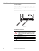
(2) Apply counter torque to the nut on the other side of terminations when tightening or loosening the terminal bolt to avoid damage to the terminal.
(3) Not all terminals present on all drives.
(4) Refer to the terminal block label inside the drive.
(5) If necessary, two wires can be used in parallel to any of these terminals using two lugs.
(6) Auxiliary power: UL Installation - 300V DC, ±10%, Non UL Installation - 270…600V DC, ±10%. Frame 1…6, 100 W.