
Installation Instructions Owner's manual

Rockwell Automation Publication 20D-IN024C-EN-P - July 2013 29
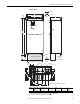
PowerFlex 700S Adjustable Frequency AC Drive - Phase II Control
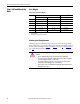
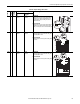
Table 11 - Jumper Settings and Locations
Frame
Voltage
Code
Current
Rating
Factory Default Jumper Settings Power Source Type
MOV/Input Filter
Caps
DC Bus Common
Mode Caps
1 B
C
D
E
All PE_B
Installed
PE_A
Installed
Solid Ground
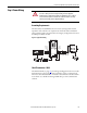
• Remove the I/O Cassette (refer to the Installation
Instructions for details). Verify that jumpers are
installed at the “PE_A” and “PE_B” locations on
the Power Board.
Non-Solid Ground
• Remove the I/O Cassette (refer to the Installation
Instructions for details). Remove jumpers at the
“PE_A” and “PE_B” locations on the Power Board.
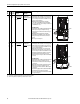
2 B
C
D
E
All PE_MOV
Installed
PE_CAP
Installed
Solid Ground
• Verify that jumpers are installed at the “PE_CAP”
and “PE_MOV” locations.
Non-Solid Ground
• Remove jumpers at the “PE_CAP” and “PE_MOV”
locations.
3 & 4 B
C
D
E
All PE_MOV
Installed
PE-CAP
Installed
Solid Ground
• Verify that jumpers are installed at the “PE_CAP”
and “PE_MOV” locations.
Non-Solid Ground
• Remove jumpers at the “PE_CAP” and “PE_MOV”
locations.
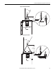
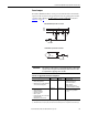
BR1
BR2
DC+
DC–
PE
U/T1
V/T2
W/T3
R/L1
S/L2
T/L3
Use 75C Wire Only
#10-#14 AWG
Torque to 7 in-lbs
!
DANGER
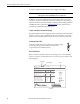
PE A
PE B
CM Cap
MOV
BR1 BR2 DC+ DC- U/T1 V/T2 W/T3
SHLD SHLD
PE R/L1 S/L2 T/L3
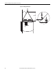
PE 2
MOV-PE JMPR
PE 1
AUX IN+ AUX OUT–
75C Cu Wire
6 AWG [10MM
2
] Max.
12 IN. LBS.
1.4 N-M
} TORQUE
WIRE
STRIP
CONTROL
POWER
PE 4
PE 3
MOV
PE_MOV
CM Cap
PE_CAP
BR1 BR2 DC+ DC- U/T1 V/T2 W/T3 R/L1 S/L2 T/L3
PE MOV
PE CAP
75C Cu Wire
3 AWG [2 5MM
2
] Max.
16 IN. LBS.
1.8 N-M
} TORQUE
WIRE
STRIP
CONTROL
POWER
AUX I N
+ –
SHLD
SHLD
PE
75C Cu Wire
6 AWG [10MM
2
] Max.
BR1 BR2
12 IN. LBS.
1.4 N-M
} TORQUE
PE_CAP
PE_MOV
CM Cap
MOV