Installation Instructions PowerFlex 700S Adjustable Frequency Drive - Phase II Control Frames 1…6 0.75…132 kW (1…200 Hp) Introduction This document explains the 5 primary steps for mechanical installation and for connecting incoming power, the motor, and basic I/O to the PowerFlex® 700S adjustable frequency AC drive with Phase II control. The information provided is intended for qualified installers only.
PowerFlex 700S Adjustable Frequency AC Drive - Phase II Control 2 Rockwell Automation Publication 20D-IN024C-EN-P - July 2013
PowerFlex 700S Adjustable Frequency AC Drive - Phase II Control Table of Contents Additional Resources . . . . . . . . . . . . . . . . . . . . . . . . . . . . . . . . . . . . . . . . . . . . . . . . . . 5 Step 1: Read the General Precautions Qualified Personnel . . . . . . . . . . . . . . . . . . . . . . . . . . . . . . . . . . . . . . . . . . . . . . . . . . . . . . 6 Personal Safety. . . . . . . . . . . . . . . . . . . . . . . . . . . . . . . . . . . . . . . . . . . . . . . . . . . . . . . . . . .
PowerFlex 700S Adjustable Frequency AC Drive - Phase II Control Step 5: Control and I/O Wiring Control and I/O Wiring Recommendations. . . . . . . . . . . . . . . . . . . . . . . . . . . . . . . 52 Main Control Board DIP Switch Settings . . . . . . . . . . . . . . . . . . . . . . . . . . . . . . . . . 53 Hardware Enable Circuitry . . . . . . . . . . . . . . . . . . . . . . . . . . . . . . . . . . . . . . . . . . . . . . 54 I/O Terminals . . . . . . . . . . . . . . . . . . . . . . . . . . . . . . . . . . .
PowerFlex 700S Adjustable Frequency AC Drive - Phase II Control Additional Resources These documents contain additional information concerning related products from Rockwell Automation.
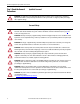
PowerFlex 700S Adjustable Frequency AC Drive - Phase II Control Step 1: Read the General Precautions Qualified Personnel ATTENTION: Only qualified personnel familiar with adjustable frequency AC drives and associated machinery should plan or implement the installation, startup and subsequent maintenance of the system. Failure to comply may result in personal injury and/or equipment damage.
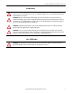
PowerFlex 700S Adjustable Frequency AC Drive - Phase II Control Product Safety ATTENTION: An incorrectly applied or installed drive can result in component damage or a reduction in product life. Wiring or application errors such as under sizing the motor, incorrect or inadequate AC supply, or excessive surrounding air temperatures may result in malfunction of the system. ATTENTION: This drive contains ESD (Electrostatic Discharge) sensitive parts and assemblies.
PowerFlex 700S Adjustable Frequency AC Drive - Phase II Control Catalog Number Explanation Step 2: Prepare for Installation Position 1-3 4 5-7 8 9 20D D 2P1 A 0 E Y N A N A N E a b c d e f g h i j k l m 11 12 13 14 15 16 a c2 c4 Drive ND Rating ND Rating 400V, 50 Hz Input Code Type 20D PowerFlex 700S b Voltage Rating Code Voltage Ph. B § 240V AC 3 (6 pulse) Prechg. _ C § 400V AC 3 (6 pulse) _ 600V, 60 Hz Input 17 ♣ Code 2P1 Amps 2.1 kW 0.
PowerFlex 700S Adjustable Frequency AC Drive - Phase II Control Catalog Number Explanation, Continued j Documentation Code Documents Code E N English Manual No Documentation N g Brake Code None N DPI ControlNet (Coax) A DPI DeviceNet B Stegmann Hi-Resolution Encoder E DPI EtherNet/IP C Multi-Device Interface 1 DriveLogix ControlNet (Coax) E 2nd Encoder DriveLogix ControlNet Redundant (Coax) S Safe-Off (w/2nd Encoder) Y Ye s N No 3 DriveLogix ControlNet (Fiber) 4 DriveLogix
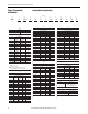
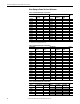
PowerFlex 700S Adjustable Frequency AC Drive - Phase II Control Drive Rating to Frame Size Cross References Table 1 - 208/240 Volt AC Input, Six Pulse Drives 208V AC Input (1) Cat. No. Normal Duty kW Rating 20DB4P2 0.75 20DB6P8 1.5 20DB9P6 2.2 20DB015 4.0 20DB022 5.5 20DB028 7.5 20DB042 11 20DB052 15 20DB070 18.5 20DB080 22 20DB104 30 20DB130 37 20DB154 45 20DB192 55 20DB260 66 Heavy Duty kW Rating 0.55 1.1 1.5 3.0 4.0 5.5 7.5 11 15 18.5 22 30 37 45 55 240V AC Input Cat. No.
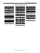
PowerFlex 700S Adjustable Frequency AC Drive - Phase II Control 600V AC Input Cat. No. Normal Duty Hp Rating 20DE011 10 20DE017 15 20DE022 20 20DE027 25 20DE032 30 20DE041 40 20DE052 50 20DE062 60 20DE077 20DE099 20DE125 20DE144 75 100 125 150 690V AC Input Heavy Duty Hp Cat. No. Normal Duty Rating kW Rating 7.5 10 15 20 25 30 40 50 20DF052 45 20DF060 55 60 20DF082 75 75 20DF098 90 100 20DF119 110 125 20DF142 132 Heavy duty kW Rating 37.
PowerFlex 700S Adjustable Frequency AC Drive - Phase II Control 540V DC Input Cat. No. Normal Duty kW Rating 20DH170 90 20DH205 110 20DH260 132 Heavy Duty kW Rating 75 90 110 650V DC Input Cat. No. Normal Duty HP Rating 20DJ156 125 20DJ180 150 20DJ248 200 Heavy Duty HP Rating 100 125 150 Frame Size 6 6 6 Table 6 - 810/932 Volt DC Input Drives 810V DC Input Cat. No. Normal Duty Hp Rating 20DE1P7 1.0 20DE2P7 2.0 20DE3P9 3.0 20DE6P1 5.0 20DE9P0 7.
PowerFlex 700S Adjustable Frequency AC Drive - Phase II Control General Considerations • If the adhesive label is removed from the top of the drive, the drive must be installed in an enclosure with side openings less than 12.5 mm (0.5 in.) and top openings less than 1.0 mm (0.04 in.) to maintain compliance with the LV Directive. • The motor cable should be kept as short as possible to avoid electromagnetic emission as well as capacitive currents.
PowerFlex 700S Adjustable Frequency AC Drive - Phase II Control Common Bus and Precharge Considerations The following notes must be read and understood. Also refer to Selecting/ Verifying Fan Voltage (Frames 5 and 6 Only) on page 34 through Power Terminal Blocks on page 41 for additional common bus information. 1. If drives without internal precharge are used (frames 5 and 6 only), then: a. precharge capability must be provided in the system to guard against possible damage, and b.
PowerFlex 700S Adjustable Frequency AC Drive - Phase II Control IMPORTANT PowerFlex 700S drives must be mounted in a clean, dry location. Contaminants such as oils, corrosive vapors and abrasive debris must be kept out of the enclosure. These enclosures are intended for indoor use primarily to provide a degree of protection against contact with enclosed equipment. These enclosures offer no protection against airborne contaminants.
PowerFlex 700S Adjustable Frequency AC Drive - Phase II Control Approximate Dimensions Figure 2 - Frames 1…3 Frame 1 Shown AA A 5.8 (0.23) dia. B 15.0 (0.59) D C 5.5 (0.22) E 312 (12.28) 8.0 (0.31) Dimensions are in millimeters and (inches) Frame (1) Slim Cassette Expanded Cassette A AA 1 135.0 (5.31) 166.9 (6.57) 2 222.0 (8.74) 253.9 (9.99) 3 222.0 (8.74) 253.9 (9.99) B C D E 336.0 (13.23) 342.5 (13.48) 517.5 (20.37) 200.0 (7.87) 200.0 (7.87) 200.0 (7.87) 105.0 (4.13) 192.0 (7.56) 192.0 (7.
PowerFlex 700S Adjustable Frequency AC Drive - Phase II Control Figure 3 - Bottom Views, Frames 1…3 Frame 1 Frame 2 167.5 (6.59) 108.5 (4.27) 87.5 (3.44) 67.5 (2.66) 47.5 (1.87) 156.9 (6.18) 22.2 (0.87) Dia. 3 Places 28.6 (1.13) Dia. 28.7 (1.13) Dia. 3 Places 22.4 (0.88) Dia. 2 Places 25.5 (1.00) 184.8 (7.28) 162.3 (6.39) 187.6 (7.39) 157.5 (6.20) 185.1 (7.29) 150.9 (5.94) 133.3 (5.25) 112.1 (4.41) 43.0 (1.69) 39.3 (1.55) 70.0 (2.76) 75.9 (2.99) 96.0 (3.78) 57.2 (2.25) 72.7 (2.86) 106.
PowerFlex 700S Adjustable Frequency AC Drive - Phase II Control Figure 4 - Frame 4 AA A D 13.0 (0.55) C 15.1 (0.59) 7.0 (0.28) 2 Places 312 (12.28) S B E 7.0 (0.28) 3 Places Lifting Holes 4 Places 8.0 (0.31) Bottom View 28.7 (1.13) Dia. 2 Places 76.0 (2.99) 65.3 (2.57) 22.2 (0.87) Dia. 47.0 (1.85) Dia. 2 Places 54.1 (2.13) Dia. 2 Places 189.7 (7.47) 177.9 (7.00) 157.9 (6.21) 141.9 (5.59) 105.1 (4.14) 26.8 (1.06) 36.8 (1.45) 50.7 (2.00) 63.8 (2.51) 112.0 (4.41) 180.0 (7.
PowerFlex 700S Adjustable Frequency AC Drive - Phase II Control Figure 5 - Frame 5, 75 Hp, 480V (55kW, 400V) 6.5 (0.26) AA A 37.6 (1.48) 15.0 (0.59) 259.1 (10.20) Detail D B C 312 (12.28) E S CAUTION HOT surfaces can cause severe burns Lifting Holes - 4 Places 12.7 (0.50) Dia. 6.5 (0.26) 12.5 (0.49) Bottom View 104.0 (4.09) 93.2 (3.67) 34.9 (1.37) Dia. 2 Places 22.2 (0.87) Dia. 2 Places 62.7 (2.47) Dia. 2 Places 241.9 (9.52) 229.5 (9.04) 220.0 (8.66) 184.0 (7.24) 159.5 (6.28) 96.0 (3.
PowerFlex 700S Adjustable Frequency AC Drive - Phase II Control Figure 6 - Frame 5, 100 Hp, 480V (55kW, 400V) AA 6.5 (0.3) A 20.5 (0.8) 259.1 (10.20) 15.0 (0.6) 37.6 (1.48) D Detail 4 x Ø 12.7 (0.5) C B E 617.0 (24.3) 625.0 (24.6) 13.0 (0.5) 12.0 (0.5) 13.0 (0.5) 27.6 (1.1) Bottom View 34.9 (1.37) Dia. 42.6 (1.68) 31.9 (1.26) 22.2 (0.87) Dia. 2 Places 62.7 (2.47) Dia. 2 Places Removable Junction Box 241.9 (9.52) 223.5 (8.80) 188.5 (7.42) 184.3 (7.26) 153.5 (6.04) 96.0 (3.78) 28.0 (1.
PowerFlex 700S Adjustable Frequency AC Drive - Phase II Control Figure 7 - Frame 6 8.5 (0.33) A 360.6 (14.20) D 49.6 (1.95) 18.0 (0.71) Detail C B E Detail 126.3 (4.97) 13.5 (0.53) Lifting Holes 4 Places 12.7 (0.50) Dia. Old Style Junction Box New Style Junction Box 56.2 (2.21) 45.6 (1.80) 8.5 (0.33) 34.9 (1.37) Dia. 3 Places 62.7 (2.47) Dia. 3 Places 22.2 (0.87) Dia. 4 Places Removable Junction Box 242.0 (9.53) 219.0 (8.62) 222.3 (8.75) 185.4 (7.30) 148.5 (5.85) 116.6 (4.59) 151.8 (5.
PowerFlex 700S Adjustable Frequency AC Drive - Phase II Control Step 3: Lift and Mount the Drive Drive Weights Table 9 - Approximate Drive Weights Frame Size Drive Weight (1) Drive Rating kW Hp kg (lb) 1 0.75…11 1…10 7.0 (15.5) 2 7.5…18.5 10…25 12.5 (27.6) 3 11…37 15…50 18.6 (40.9) 4 25…60 18.5…55 24.5 (54.0) 5 40…100 30…90 37.2 (82.0) 6 60…200 45…132 71.5 (157.
PowerFlex 700S Adjustable Frequency AC Drive - Phase II Control Figure 8 - Lifting Frame 4 Drives < 45° >1/2 A A S Figure 9 - Lifting Frame 5 Drives < 45° >1/2 A A S Rockwell Automation Publication 20D-IN024C-EN-P - July 2013 23
PowerFlex 700S Adjustable Frequency AC Drive - Phase II Control Figure 10 - Lifting Frame 6 Drives < 45° >1/2 A A 24 Rockwell Automation Publication 20D-IN024C-EN-P - July 2013
PowerFlex 700S Adjustable Frequency AC Drive - Phase II Control Step 4: Power Wiring ATTENTION: National Codes and standards (NEC, VDE, BSI and so forth) and local codes outline provisions for safely installing electrical equipment. Installation must comply with specifications regarding wire types, conductor sizes, branch circuit protection and disconnect devices. Failure to do so may result in personal injury and/or equipment damage.
PowerFlex 700S Adjustable Frequency AC Drive - Phase II Control Unbalanced, Ungrounded or Resistive Grounded Distribution Systems If phase to ground voltage will exceed 125% of normal or the supply system is ungrounded, refer to Wiring and Grounding Guidelines for Pulse Width Modulated (PWM) AC Drives, publication DRIVES-IN001, for more information. ATTENTION: PowerFlex 700S drives contain protective MOVs and common mode capacitors that are referenced to ground.
PowerFlex 700S Adjustable Frequency AC Drive - Phase II Control Power Jumpers PowerFlex 700S Phase II drives contain protective MOVs and Common Mode Capacitors that are referenced to ground (see below). To guard against unstable operation and/or damage, the drive must be properly configured as shown in Table 10 on page 27.
PowerFlex 700S Adjustable Frequency AC Drive - Phase II Control To connect or disconnect these devices, refer to pages 29 through 32. IMPORTANT Common mode capacitors are required to conform with the EMC directive. Removing these devices will withdraw the associated directive. In addition, on an ungrounded distribution system where the line-to-ground voltages on any phase could exceed 125% of the nominal line-to-line voltage, an isolation transformer should be installed.
PowerFlex 700S Adjustable Frequency AC Drive - Phase II Control Frame Voltage Code Current Rating Table 11 - Jumper Settings and Locations 1 B C D E All Factory Default Jumper Settings MOV/Input Filter DC Bus Common Caps Mode Caps PE_B PE_A Installed Installed Power Source Type Solid Ground • Remove the I/O Cassette (refer to the Installation Instructions for details). Verify that jumpers are installed at the “PE_A” and “PE_B” locations on the Power Board.
Frame Voltage Code Current Rating PowerFlex 700S Adjustable Frequency AC Drive - Phase II Control 5 C F W 052 060 140 Factory Default Jumper Settings Power Source Type MOV/Input Filter DC Bus Common Caps (1) (2) Mode Caps Two green/yellow Green/yellow wire to Solid Ground wires connected to CM Cap Board is 1. CM Cap jumper wire should be connected to ground with a metal screw. Verify. If necessary, remove the the Power Terminal connected to ground nylon screw/spacer and insert a metal M5 x 8 screw.
PowerFlex 700S Adjustable Frequency AC Drive - Phase II Control Frame Voltage Code Current Rating Factory Default Jumper Settings Power Source Type MOV/Input Filter DC Bus Common Caps (1) (2) Mode Caps Two green/yellow All, Green/yellow wire is Solid Ground except wires connected to connected to ground 1. CM Cap jumper wire should be connected to ground with a metal screw. Verify.
Voltage Code Current Rating 6 B C D H J N P R All Factory Default Jumper Settings MOV/Input Filter DC Bus Common Caps (1) (2) Mode Caps Two green/yellow Green/yellow wire to wires connected to CM Cap Board is Power Terminal connected to Power Block “PE” Terminal Block “PE” Power Source Type Solid Ground 1. The green/yellow CM Cap jumper wire should be connected to “PE.” 2. The MOV/Input Filter Cap jumper wires should be connected to “PE.
PowerFlex 700S Adjustable Frequency AC Drive - Phase II Control AC Supply Source Considerations PowerFlex drives are suitable for use on a circuit capable of delivering up to a maximum of 200,000 rms symmetrical amperes, 600 volts with recommended s/ circuit breakers. ATTENTION: To guard against personal injury and/or equipment damage caused by improper fusing or circuit breaker selection, use only the recommended line s/circuit breakers specified in Fusing and Circuit Breakers on page 44.
PowerFlex 700S Adjustable Frequency AC Drive - Phase II Control AC Input Phase Selection (Frames 5 and 6 Only) ATTENTION: To avoid a shock hazard, be sure that all power to the drive has been removed before performing the following. Moving the “Line Type” jumper shown in Figure 12 on page 35 will select single or three-phase operation. Remove plastic guard to access jumper. IMPORTANT When selecting single-phase operation, input power must be applied to the R (L1) and S (L2) terminals only.
PowerFlex 700S Adjustable Frequency AC Drive - Phase II Control Fan VA Rating (DC Input Drives Only) Frame Fan Voltage (120V or 240V) 5 100 VA 6 138 VA Figure 12 - Phase Selection Jumper and Fan Transformer Locations (Frame 5 shown) (Frame 5 shown) Line Type Jumper 3-PH 1-PH LINE TYPE SPARE 1 SPARE 2 Optional Communications Module Fan Voltage Selection 300 VDC EXT PWR SPLY TERM (PS+, PS-) POWER TERMINAL RATINGS WIRE RANGE: 14-1/0 AWG (2.5-35 MM2) TORQUE: 32 IN-LB (3.6 N-M) STRIP LENGTH: 0.
PowerFlex 700S Adjustable Frequency AC Drive - Phase II Control Important Common Bus (DC Input) Application Notes 1. If drives without internal precharge are used (Frames 5 and 6 only), then: • precharge capability must be provided in the system to guard against possible damage, and • disconnect switches Must Not be used between the input of the drive and a common DC bus without the use of an external precharge device. 2.
PowerFlex 700S Adjustable Frequency AC Drive - Phase II Control Accessing the Terminals Figure 13 - Opening the Drive Cover Frames 1…4 Locate the slot in the upper left corner. Slide the locking tab up and swing the cover open. Special hinges allow the cover to move away from the drive and lay on top of an adjacent drive (if present). = Frame 5 Slide the locking tab up, loosen the right-hand cover screw and remove the cover.
PowerFlex 700S Adjustable Frequency AC Drive - Phase II Control Cable Entry Plate Removal If additional wiring access is needed, the cable entry plate on frame 1…3 drives can be removed. Loosen the screws securing the plate to the chassis and slide the plate down and off the drive. IMPORTANT Removing the cable entry plate on frame 1…3 limits the maximum surrounding air temperature to 40 °C (104 °F).
PowerFlex 700S Adjustable Frequency AC Drive - Phase II Control Power Wire Recommendations Type Power (1)(2) Description Standard Min Insulation Rating 600V, 75 °C (167 °F) • Four tinned copper conductors with XLPE insulation. • Copper braid/aluminum foil combination shield and tinned copper drain wire. • PVC jacket. (1) Control and signal wires should be separated from power wires by at least 0.3 meters (1 foot).
PowerFlex 700S Adjustable Frequency AC Drive - Phase II Control Figure 14 - Typical Power Terminal Block Locations Frame 2 Frame 1 Frames 3 & 4 PE B PE A 3 12 IN. LBS. 1.4 N-M } TORQUE AUX IN + – Use 75C Wire Only #10-#14 AWG Torque to 7 in-lbs 1 POWER 75C Cu Wire 3 AWG [25MM2] Max. 16 IN. LBS. 1.8 N-M } TORQUE CONTROL WIRE STRIP BR1 BR2 75C Cu Wire 6 AWG [10MM2] Max.
PowerFlex 700S Adjustable Frequency AC Drive - Phase II Control Figure 15 - Power Terminal Blocks BR1 BR2 DC+ DC– PE Frame 1 Frame 2 BR1 BR2 DC+ DC– PE U (T1) V (T2) W (T3) R (L1) S (L2) T (L3) U V W R S T (T1) (T2) (T3) (L1) (L2) (L3) Frame 3 Motor BR1 BR2 DC+ DC– U V W R S T (T1) (T2) (T3) (L1) (L2) (L3) Input AC Line PS– BR1/ BR2 DC+ DC+ DC– U/T1 V/T2 W/T3 PE PE R/L1 S/L2 T/L3 Frame 5 - 75 HP, Normal Duty 480V AC Input PS+ BR2 DC+ BR1/ DC+ DC– U/T1 V/T2 R/L1 W/T3 PE S/L2 T/L3 PE
PowerFlex 700S Adjustable Frequency AC Drive - Phase II Control Terminal BR1 BR2 DC+ DC– PE U V W R S T Description DC Brake (+) DC Brake (–) DC Bus (+) DC Bus (–) PE Ground Motor Ground U (T1) V (T2) W (T3) R (L1) S (L2) T (L3) Notes Dynamic Brake Resistor Connection (+) Dynamic Brake Resistor Connection (–) DC Input Power or Dynamic Brake Chopper DC Input Power or Dynamic Brake Chopper Refer to Figure 14 on page 40 for location on 3 Frame drives Refer to Figure 14 on page 40 for location on 3 Frame dri
PowerFlex 700S Adjustable Frequency AC Drive - Phase II Control Using Input/Output Contactors It is recommended that the auxiliary relay of the output contactor (when used) be wired in series with Digital Input 6 and that Digital Input 6 be configured as a hardware enable input. See Hardware Enable Circuitry on page 54 for more information. ATTENTION: A contactor or other device that routinely disconnects and reapplies the AC line to the drive to start and stop the motor can cause drive hardware damage.
PowerFlex 700S Adjustable Frequency AC Drive - Phase II Control Regenerative Unit to Drive Connections Regenerative Brake Mode Frame(s) Terminals 1336 REGEN 1…4 DC+ & DC5&6 DC+ & DC- PowerFlex 700S BR1 & DCDC+ & DC- Regenerative Bus Supply Mode Frame(s) Terminals 1336 REGEN 1…4 DC+ & DC5&6 DC+ & DC- PowerFlex 700S DC+ & DCDC+ & DC- of Common Bus Drives Electronic Motor Overload Protection Provides class 10 motor overload protection according to NEC article 430 and motor over-temperature protection acco
PowerFlex 700S Adjustable Frequency AC Drive - Phase II Control Circuit Breakers The “non-” listings in the following tables include inverse time circuit breakers, instantaneous trip circuit breakers (motor circuit protectors) and 140M selfprotected combination motor controllers. If one of these is chosen as the desired protection method, the following requirements apply: • IEC – Both types of circuit breakers and 140M self-protected combination motor controllers are acceptable for IEC installations.
PowerFlex 700S Adjustable Frequency AC Drive - Phase II Control Table 13 - 240 Volt AC Input Frames 1…6 Drive Protection Devices Frame Drive Cat. No. HP Rating Input Ratings ND Amps HD kVA Dual Element Time Delay Fuse Non-Time Delay Fuse Circuit Breaker (3) Motor Circuit Protector (5) 140M Motor Starter with Adjustable Current Range (6)(7) Min (1) Min (2) Max (4) Max (5) Available Cat. No.s (8) Max (2) Max (3) Minimum Enclosure Volume (in.3)(9) 20DB4P2 1 1 0.75 3.3 1.
PowerFlex 700S Adjustable Frequency AC Drive - Phase II Control 20DC085 (1) 20DC105 20DC205 20DC260 140M Motor Starter with Adjustable Current Range (8)(9) kVA Min (3) Max (4) Min (5) Max (6) Max (6) Max (8) Available Cat. No.s (10) 81.4 56.4 110 200 110 300 300 150 – – – – 68.9 47.8 90 175 90 275 300 100 – – – – – 100.5 69.6 125 225 125 400 300 150 – – – – 45 81.4 56.4 110 175 110 300 300 150 – – – – 55 – 121.1 83.
HP Rating Input Ratings Dual Element Time Delay Fuse Non-Time Delay Fuse Circuit Breaker (3) Motor Circuit Protector (5) 140M Motor Starter with Adjustable Current Range (6)(7) Frame PowerFlex 700S Adjustable Frequency AC Drive - Phase II Control ND HD Amps kVA Min (1) Max (2) Min (3) Max (4) Max (4) Max (6) Available Cat. No.s (8) 5 100 – 117 97.6 150 250 150 500 375 150 – – – – – 75 90.1 74.9 125 200 125 350 350 125 – – – – Drive Cat. No.
PowerFlex 700S Adjustable Frequency AC Drive - Phase II Control Table 17 - 690 Volt AC Input Frames 5 & 6 Drive Protection Devices 20DF052 kW Rating Non-Time Delay Fuse Circuit Breaker (3) Motor Circuit Protector (5) ND HD Amps kVA Min (1) Max (2) Min (2) Max (3) Max (4) Max (5) 45 – 46.9 59.5 60 110 60 175 175 – – 37.5 40.1 48.0 50 90 50 150 150 – 55 – 57.7 68.9 80 125 80 225 225 – – 45 46.9 59.5 60 110 60 175 175 – 75 – 79.0 94.
PowerFlex 700S Adjustable Frequency AC Drive - Phase II Control Table 19 - 540 Volt DC Input Frames 1…6 Drive Protection Devices Drive Cat. No. Frame kW Rating 20DC3P5 20DC5P0 20DC8P7 20DC011 20DC015 20DC022 20DC030 20DC037 20DC043 20DC056 20DC072 20DC085 20DH105 (1) 1 1 1 1 1 1 2 2 3 3 3 4 5 20DH125 (1) 5 20DH140 5 20DH170 (1) 6 20DH205 (1) 6 20DH260 (1) 6 DC Input Ratings ND HD Amps 1.5 2.2 4 5.5 7.5 11 15 18.5 22 30 37 45 55 – 55 – 75 – 90 – 110 – 132 – 1.1 1.5 3.0 4 5.5 7.5 11 15 18.
PowerFlex 700S Adjustable Frequency AC Drive - Phase II Control Drive Cat. No. Frame HP Rating ND HD DC Input Ratings Amps Fuse Non-Time Delay (2) 20DJ180 (1) 6 20DJ248 (1) 6 150 – 200 – 198 171.2 272 198 400 400 400 400 HSJ400 HSJ400 HSJ400 HSJ400 – 125 – 150 (1) Also applies to “R” voltage class. s must be applied in the (+) leg and (-) leg of the DC Common Bus.
PowerFlex 700S Adjustable Frequency AC Drive - Phase II Control Step 5: Control and I/O Wiring Important points to remember about control and I/O wiring: • Always use copper wire. • Wire with an insulation rating of 600V or greater is recommended. • Control and signal wires should be separated from power wires by at least 0.3 meters (1 foot). • For CE compliance, 115 volt digital input wiring must be shielded or must not exceed 30 meters (98 feet) in length.
PowerFlex 700S Adjustable Frequency AC Drive - Phase II Control Main Control Board DIP Switch Settings ATTENTION: The DIP switches for Digital Inputs 4…6 are set to 24V DC at the factory. If you are running a 115V AC input application, the switches must be set as indicated below before applying power to the drive or damage to the main control board may occur.
PowerFlex 700S Adjustable Frequency AC Drive - Phase II Control Figure 17 - Main Control Board Dip Switches SWITCH S1 RUN PROG REMOTE Down Up Center JUMPER P22 4 2 SWITCH S5 4 2 SIDE VIEW 3 1 3 1 = HW Enable = No HW Enable FRONT TOP VIEW Up = Open = Off 1 2 Down = Closed = On JUMPER P13 16 16 SWITCH S2 SIDE VIEW Up = Open = Off Down = Closed = On = Gate Disabled = Gate Enabled 1 2 15 15 FRONT TOP VIEW 3 4 SWITCH S4 SIDE VIEW SWITCH S3 SIDE VIEW Up = Open = Off FRONT TOP VIEW
PowerFlex 700S Adjustable Frequency AC Drive - Phase II Control I/O Terminals Terminal blocks TB1 and TB2 contain connection points for all inputs, outputs and standard encoder connections. When installed, both terminal blocks reside on the main control board. These components are provided with the drive but are not factory installed. Make the terminal block wire connections. IMPORTANT For NEMA/UL Type 1 applications, all wiring must be routed through the conduit plate on the drive.
PowerFlex 700S Adjustable Frequency AC Drive - Phase II Control Table 25 - TB1 Terminals 1 2 3 4 5 6 7 8 9 10 11 12 13 14 15 16 17 18 19 20 21 22 23 24 Terminal Signal Factory Default Description 1 2 3 4 5 6 7 8 9 10 11 12 13 14 15 16 17 18 19 20 21 22 23 24 (Volt) Bipolar, differential input, ±10V, 0…20 mA, 13 bit + sign 20 kΩ impedance at Volt; 500 Ω impedance at mA(1) 800 NA (Volt) Analog Input Shield Bipolar, differential input, ±10V, 0…20 mA, 13 bit + sign 20 kΩ impedance at Volt; 500 Ω imp
PowerFlex 700S Adjustable Frequency AC Drive - Phase II Control I/O Wiring Examples Table 27 - TB1 Analog Input/Output and Encoder Wiring Examples Input/Output Connection Example Potentiometer Unipolar Speed Reference 0…10V Analog Input Internal Source Required Parameter Changes NA 13 1 14 2 15 3 16 4 17 5 18 6 19 7 20 8 21 9 22 10 23 11 24 12 NA Potentiometer Bi-polar Speed Reference ±10V Analog Input Internal Source Unipolar Speed Reference 0…10V Analog Input External Source 1
PowerFlex 700S Adjustable Frequency AC Drive - Phase II Control Input/Output Connection Example Primary Encoder Interface Internal Supply Supports 5V DC or 12V DC differential encoders 13 with internal power supply. 14 Used as primary closed loop feedback.
PowerFlex 700S Adjustable Frequency AC Drive - Phase II Control Table 28 - TB2 Digital Input/Output Wiring Examples Input/Output Connection Example Digital Inputs used for enable and Sourcing Digital Inputs - Internal Power Supply precharge control. Com 1 Note: 24V DC supply - supports only on-board 24V dc digital inputs. Do not use for circuits outside the 2 drive. 3 Note: The factory default for all digital inputs is 24V DC. To use 115V AC on digital inputs 4…6 see Table 23 on page 53.
PowerFlex 700S Adjustable Frequency AC Drive - Phase II Control Input/Output Digital Outputs used with 24V DC Relays External Power Supply Connection Example Sourcing Digital Outputs 24V DC Common 1 Note: Digital Inputs 1-3 are always 12V or 24V DC. 2 3 4 5 • Sourcing a Digital Output - The digital output common (return) is connected to the power supply common.
PowerFlex 700S Adjustable Frequency AC Drive - Phase II Control DriveLogix 5730 Controller Option Refer to the DriveLogix 5730 Controller for PowerFlex 700S Drives with Phase II Control User Manual, publication 20D-UM003, for details on using and configuring this option. IMPORTANT The DriveLogix controller option ships with the battery installed, but disconnected. You must connect the battery while installing the drive.
PowerFlex 700S Adjustable Frequency AC Drive - Phase II Control Second Encoder Feedback Option Second Encoder Feedback Option Specifications Consideration Input Encoder Voltage Supply Maximum Input Frequency Description Dual Channel Plus Marker, Isolated with differential transmitter Output (Line Drive) Incremental, Dual Channel Quadrature type 5V DC or 12V DC 320 mA per channel 5V DC requires an external power supply. 12 V DC minimum high state voltage of 7V DC, maximum low state voltage of 0.
PowerFlex 700S Adjustable Frequency AC Drive - Phase II Control Second Encoder Feedback Option Wiring Examples Differential Encoder with Internal Supply Encoder P1 1 2 3 4 5 6 7 8 9 10 11 12 13 A Not A B Not B Z Not Z Power Common N/C N/C N/C N/C A Not A B Not B Z Not Z Power Common Shield Differential Encoder with External Supply Encoder P1 1 2 3 4 5 6 7 8 9 10 11 12 13 A Not A B Not B Z Not Z Power Common N/C N/C N/C N/C A Not A B Not B Z Not Z Power Common Shield Power Common Second Encoder Fee
PowerFlex 700S Adjustable Frequency AC Drive - Phase II Control Stegmann Hi-Resolution Encoder Feedback Option Stegmann Hi-Resolution Encoder Feedback Option Specifications Consideration Encoder Voltage Supply Hi-Resolution Feedback Maximum Cable Length Maximum Frequency (Encoder Speed) Description 11.5V DC @ 130 mA Sine/Cosine 1V P-P Offset 2.5 90 m (295 ft) 12.5 μs/cycle (4687.
PowerFlex 700S Adjustable Frequency AC Drive - Phase II Control Wiring the Stegmann Hi-Resolution Feedback Option Card to an Encoder Terminal block P1 contains connection points for a Stegmann Hiperface® encoder. This terminal block resides on the Hi-Resolution Encoder Feedback Option card. Remember to route wires through the sliding access panel at the bottom of the control assembly.
PowerFlex 700S Adjustable Frequency AC Drive - Phase II Control Recommended Cables and Wiring Diagrams for the Stegmann Hi-Resolution Feedback Option Card If you are using this motor and feedback device: Allen-Bradley MPL-A/B3xx, -A/B4xx, -A/B45xx, -A/B5xx, and -A/B6xx motors with embedded Stegmann rotary encoder Allen-Bradley MPL-A/B3xx, -A/B4xx, -A/B45xx, -A/B5xx, and -A/B6xx motors with embedded Stegmann rotary encoder HPK-Series motors with embedded Stegmann rotary encoder Allen-Bradley 1326AB-BXXXX-21
PowerFlex 700S Adjustable Frequency AC Drive - Phase II Control Stegmann Hi-Resolution Feedback Option Card Connection Examples Figure 20 - HPK-Series motors with 2090-XXNFMF-SXX cable Note: Thermal switch cannot be accessed by using 2090-XXNFMF-SXX cable.
PowerFlex 700S Adjustable Frequency AC Drive - Phase II Control Stegmann Hi-Resolution Feedback Option Card Connection Examples Figure 23 - MPL-A5xx and all MPL-Bxxx Motor or 1326AB-BXXXX-M2L, -M2KXL, -S2L, and -S2KXL motor with 2090-XXNFMP-SXX cable Note: Thermal switch cannot be accessed by using 2090-XXNFMP-SXX cable.
PowerFlex 700S Adjustable Frequency AC Drive - Phase II Control Stegmann Hi-Resolution Feedback Option Card Connection Examples Figure 26 - Stegmann shielded twisted-pair cable with 12-pin DIN style connector ENCODER Hi-Res Feedback Option Board POWER COMMON 12 POWER 11 REFSIN 10 +SIN 9 REFCOS 8 +COS 7 SHIELD 6 SHIELD 5 N/C 4 N/C 3 DATA+ (RS 485) 2 DATA- (RS 485) 1 RD BU RD BN WH BK BU PK GN BN WH PK GY GY BK GN 12 11 10 9 8 7 6 5 4 3 2 1 POWER N/C POWER COMMON SHIELD +COS DATA- (RS 485) REFSIN +
PowerFlex 700S Adjustable Frequency AC Drive - Phase II Control Stegmann Hi-Resolution Feedback Option Card Connection Examples Figure 29 - Pre-attached Stegmann shielded twisted-pair cable ENCODER Hi-Res Feedback Option Board POWER COMMON 12 POWER 11 REFSIN 10 +SIN 9 REFCOS 8 +COS 7 SHIELD 6 SHIELD 5 N/C 4 N/C 3 DATA+ (RS 485) 2 DATA- (RS 485) 1 BU RD BN WH BK RD BU BN PK GN WH PK BK GY 1 POWER 2 3 4 5 6 7 8 POWER COMMON REFSIN REFCOS DATA+ (RS 485) DATA- (RS 485) +SIN +COS GY GN Resolver Feed
PowerFlex 700S Adjustable Frequency AC Drive - Phase II Control Allen-Bradley servo motors may be ordered with factory installed resolvers. The list of factory installed resolvers below are supported by the 700S Resolver Feedback Option card.
PowerFlex 700S Adjustable Frequency AC Drive - Phase II Control Resolver Feedback Option Terminal Designations 1 2 3 4 5 6 7 8 Terminal 1 2 3 4 5 6 7 8 Signal COS LOW COS HIGH SIN LOW SHIELD SIN HIGH REF LOW SHIELD REF HIGH Description Negative Cosine signal Positive Cosine signal Negative Sine signal Connection point for resolver cable shield Positive Sine signal Negative Reference signal Connection point for resolver cable shield Positive Reference signal Resolver Feedback Option Connection Examples
PowerFlex 700S Adjustable Frequency AC Drive - Phase II Control Multi-Device Interface (MDI) Feedback Option MDI Option Specifications Consideration Rotary Encoder Voltage Supply Rotary Encoder Hi-Resolution Feedback Rotary Encoder Maximum Cable Length Linear Encoder Maximum Cable Length Rotary Encoder RS-485 Interface Registration Inputs Description 11.5V DC @ 130 mA Sine/Cosine 1V P-P Offset 2.
PowerFlex 700S Adjustable Frequency AC Drive - Phase II Control Rotary Encoders Supported by the MDI Option IMPORTANT Please note that encoders must be ordered as “Single Ended” so that the RS485 channel has the proper termination network installed at the factory. Rotary Encoder Model Stegmann SINCOS SCS-60, SCS-70, SCM-60, and SCM-70 Stegmann SINCOS SCS-KIT-101 and SCM-KIT-101 Stegmann SINCOS SRS-50, SRS-60, SRM-50, and SRM-60 Stegmann SINCOS SRS/SRM 25 Resolution 512 sine cycles per revolution.
PowerFlex 700S Adjustable Frequency AC Drive - Phase II Control MDI Option Card Connection Examples Figure 30 - All MPL-A/B3xx, -A/B4xx, -A/B45xx, -A/B5xx, and -B6xx motors with 2090-CFBM7E7-CDAFXX or 2090-CFBM7DF-CDAFXX cable Note: Thermal switch cannot be accessed by using 2090-CFBM7X7-CDAFXX cable.
PowerFlex 700S Adjustable Frequency AC Drive - Phase II Control MDI Option Card Connection Examples Figure 33 - Rotary Encoder connections for MPL-A5xx and MPL-Bxxx motors or 1326AB-BXXXX-M2L, -M2KXL, -S2L, and -S2KXL motors with 2090CDNFDMP-SXX cable MDI Feedback Option Board Rotary Encoder POWER COMMON Rotary Encoder POWER Rotary Encoder REFSIN Rotary Encoder +SIN Rotary Encoder REFCOS Rotary Encoder +COS Rotary Encoder DATA+ (RS485) Rotary Encoder DATA- (RS485) Linear Sensor CLOCK+ Linear Sensor CLOCKLi
PowerFlex 700S Adjustable Frequency AC Drive - Phase II Control MDI Option Card Connection Examples Figure 36 - Rotary Encoder connections for MPL-A3xx - MPL-A45xx and all MPG series motors with 2090-UXNFDMP-SXX cable MDI Feedback Option Board Rotary Encoder POWER COMMON Rotary Encoder POWER Rotary Encoder REFSIN Rotary Encoder +SIN Rotary Encoder REFCOS Rotary Encoder +COS Rotary Encoder DATA+ (RS485) Rotary Encoder DATA- (RS485) Linear Sensor CLOCK+ Linear Sensor CLOCKLinear Sensor DATA+ Linear Sensor DA
PowerFlex 700S Adjustable Frequency AC Drive - Phase II Control MDI Option Card Connection Examples Figure 39 - Rotary Encoder connections with Stegmann shielded twisted-pair cable and 8-pin Berg style connector ROTARY ENCODER MDI Feedback Option Board Rotary Encoder POWER COMMON Rotary Encoder POWER Rotary Encoder REFSIN Rotary Encoder +SIN Rotary Encoder REFCOS Rotary Encoder +COS Rotary Encoder DATA+ (RS485) Rotary Encoder DATA- (RS485) Linear Sensor CLOCK+ Linear Sensor CLOCKLinear Sensor DATA+ Linear
PowerFlex 700S Adjustable Frequency AC Drive - Phase II Control Notes: Rockwell Automation Publication 20D-IN024C-EN-P - July 2013 79
Rockwell Automation Support Rockwell Automation provides technical information on the Web to assist you in using its products. At http://www.rockwellautomation.com/support/, you can find technical manuals, a knowledge base of FAQs, technical and application notes, sample code and links to software service packs, and a MySupport feature that you can customize to make the best use of these tools.