
Owner's manual


Programming and Parameters 3-43
No.
Name
Description Values
Linkable
Read-Write
Data Type
313 Heatsink Temp
Displays the measured temperature of the drive's heatsink.
Units:
Default:
Min/Max:
degC
0.0000
-30.0000/200.0000
Real
314 VPL Firmware Rev
Displays the major and minor revision levels of the drive's Velocity Position Loop (VPL)
software.
Default:
Min/Max:
Comm Scale:
1.16
0.01/99.99
x 100
16-bit
Integer
315 VPL Build Number
Displays the build number of the drive's Velocity Position Loop (VPL) software.
Default:
Min/Max:
2
1/10000
16-bit
Integer
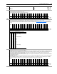
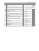
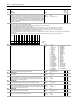
316 SynchLink Status
Indicates status of SynchLink functions.
• Bit 0 [FB Opt Prsnt] indicates the presence of an optional feedback daughter card.
• Bit 1 [Encdr0 Prsnt] indicates the presence of Encoder 0.
• Bit 2 [Encdr1 Prsnt] indicates the presence of Encoder 1.
• Bit 3 [In Sync] indicates SynchLink communications is synchronized.
• Bit 4 [Tx Active] indicates TX frames are being transmitted downstream from this node.
• Bit 5 [Rx Active] indicates RX frames are being received from nodes upstream.
• Bit 15 [Rx Data Enbl] indicates received data is being updated.
317 SL System Time
Displays the SynchLink system time counter.
Units:
Default:
Min/Max:
µSec
0
0/
1048575
32-bit
Integer
318 Posit Spd Output
Final output of the position regulator.
Units:
Default:
Min/Max:
Comm Scale:
RPM
0.0000
-/+14112.0000
Par 4 [Motor NP RPM] = 1.0
Real
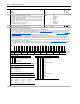
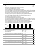
320 Exception Event1
Indicates the presence of certain drive anomalies. Configure the drive's response to these events by entering values in the parameters of the Fault/Alarm
Configuration group of the Utility file.
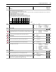
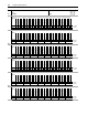
321
Exception Event2
Indicates the presence of certain drive anomalies. Configure the drive's response to these events by entering values in the parameters of the Fault/Alarm
Configuration group of the Utility file.
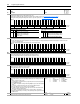
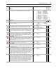
322
Exception Event3
Indicates the presence of certain drive anomalies. Configure the drive's response to these events by entering values in the parameters of the Fault/Alarm
Configuration group of the Utility file.
Options
Reserved
Reserved
Reserved
Reserved
Reserved
Reserved
Reserved
Reserved
Reserved
Reserved
Reserved
Reserved
Reserved
Reserved
Reserved
Reserved
Rx Data Enbl
Reset Req’d
Reserved
Reserved
Reserved
Reserved
Reserved
Reserved
Reserved
Reserved
Rx Active
Tx Active
In Sync
Encdr1 Prsnt
Encdr0 Prsnt
FB Opt Prsnt
Default00000000000000000000000000000000
Bit 313029282726252423222120191817161514131211109876543210
0 = False
1 = True
Options
PWM Asynchro
Precharge Er
MC Firmware
PWM Short
VPL/MC Comm
OverCurrent
Ground Fault
Trans Desat
Bus OverVolt
MC Commissn
Over Freq
Inertia Test
DSP Error
DSP Mem Err
Ext Fault In
Inv OL Trip
Inv OL Pend
Inv OTmpTrip
Inv OTmpPend
Motor Stall
Mtr OL Pend
Mtr OL Trip
Power Loss
SLink Comm
SLink HW
Ctrl EE Mem
FB Opt1 Loss
FB Opt0 Loss
Encdr1 Loss
Encdr0 Loss
SpdRef Decel
Abs OverSpd
Default00000000000000000000000000000000
Bit 313029282726252423222120191817161514131211109876543210
0 = False
1 = True
Options
Lgx LinkChng
Lgx Closed
Lgx Timeout
Lgx OutOfRun
NetLoss DPI6
NetLoss DPI5
NetLoss DPI4
NetLoss DPI3
NetLoss DPI2
NetLoss DPI1
DPI Loss P6
DPI Loss P5
DPI Loss P4
DPI Loss P3
DPI Loss P2
DPI Loss P1
No Ctrl Devc
Reserved
Interp Synch
Reserved
NonCnfgAlarm
VoltFdbkLoss
BusUnderVolt
RidethruTime
Slink Mult
PowerEE Cksm
BrakeOL Trip
PSC Sys Flt2
PSC Sys Flt1
Ctrl EE Cksm
MC Command
+/- 12v Pwr
Default00000000000000000000000000000000
Bit 313029282726252423222120191817161514131211109876543210
0 = False
1 = True
Options
Reserved
Reserved
Reserved
Reserved
Reserved
Reserved
Reserved
Reserved
Reserved
Reserved
Reserved
Posit Err
-Hrd OvrTrvl
+Hrd OvrTrvl
-Sft OvrTrvl
+Sft OvrTrvl
Reserved
Reserved
Reserved
Reserved
Reserved
HH PwrBdTemp
HH PwrEE Er
HHPrChrgCntc
HH PwrBd Prc
HH Drv Ovrld
HH FanFdbkLs
HH BusWtchDg
HH BusCRC Er
HH BusLinkLs
HH BusComDly
HH InPhaseLs
Default00000000000000000000000000000000
Bit 313029282726252423222120191817161514131211109876543210
0 = False
1 = True