
Owner's manual


3-38 Programming and Parameters
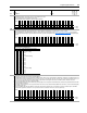
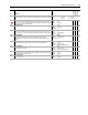
261 Hi Res0 TP Sel
Selects data displayed by Par 262 [Hi Res0 TP Data].
• H0 Edge Time - Latency counter value, not used for Hi-Resolution Feedback Option.
• H0 dEdge - Change in edge counts for one 500 microsecond update. At constant
speed, this value should be constant.
• H0 dTime - Change in update time. This value should be constant, 500 microseconds.
• H0 EPR - This value should be 1,048,576 counts per revolution - this is a constant
value.
• H0 dTheta - This is a scaled value of option 2.
• Ho Delta2Err - Derivative of option 2.
Default:
Options:
0
0
1
2
3
4
5
6
7
“Zero”
“Zero”
“H0 Edge Time”
“H0 dEdge”
“H0 dTime”
“H0 EPR”
“H0 Edge Mode”
“H0 dTheta”
“H0 Delta2Err”
262 Hi Res0 TP Data
Displays data selected by Par 261 [Hi Res0 TP Sel].
Default:
Min/Max:
0
-/+32768
16-bit
Integer
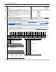
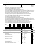
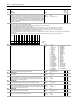
266 Reslvr0 Config
Configures options for the resolver option card at port 0.
• Setting bit 0 [Cable Tune] enables the cable tuning test, resetting the bit to zero disables the test.
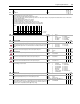
• Bits 2 [Resolution 0] and 3 [Resolution 1] select the feedback resolution (see Table 266A: Resolution Settings
). This determines the number of significant bits
that are calculated in the value of parameter 250 [FB Opt0 Posit]. It does not affect the number of counts created per resolver revolution (see Table 266B:
Resolution Setting and Least Significant Bits Used). Also, the resolution sets a limit on the maximum tracking speed (see Table 266C: Resolution and
Resolver Tracking Speed).
• Setting bit 4 [Energize] energizes the resolver, resetting the bit to zero de-energizes the resolver.
• Bit 5 [Resolver Dir] determines the counting direction. If clear, the direction is forward or up. If set, the direction is reverse or down.
• Bit 9 [Edge Time] configures the method of sampling used by the Velocity Position Loop (VPL). Setting the bit chooses "Edge to Edge" sampling, while
resetting the bit to zero chooses "Simple Difference" sampling. "Simple Difference" sampling calculates speed by examining the difference between pulse
counts over a fixed sample time. "Edge to Edge" sampling adjusts the sample time to synchronize with the position count updates from the daughter card -
improving the accuracy of the speed calculation.
• Bits 12 [SmplRate bt0] through 15 [SmplRate bt3] configure the sample interval for measuring speed (See Table 266D: Encoder Sample Interval
). Increasing
the encoder sample interval improves speed measurement near zero speed. Decreasing allows the speed control regulator to perform with high gains at
high speeds.
No.
Name
Description Values
Linkable
Read-Write
Data Type
Options
Reserved
Reserved
Reserved
Reserved
Reserved
Reserved
Reserved
Reserved
Reserved
Reserved
Reserved
Reserved
Reserved
Reserved
Reserved
Reserved
SmplRate bt3
SmplRate bt2
SmplRate bt1
SmplRate bt0
Reserved
Reserved
Edge Time
Reserved
Reserved
Reserved
Resolver Dir
Energize
Resolution 1
Resolution 0
Reserved
Cable Tune
Default00000000000000010100001000010100
Bit 313029282726252423222120191817161514131211109876543210
0 = False
1 = True
T
a
bl
e
266A
:
R
eso
l
ut
i
on
S
ett
i
ngs
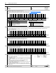
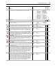
Table 266B: Resolution Setting and Least Significant Bits Used
Table 266C: Resolution and Resolver Tracking Speed
Bit 3 2 Resolution
0 0 10 bit resolution
0 1 12 bit resolution (default setting)
1 0 14 bit resolution
1 1 16 bit resolution
Resolution LSB Not Used Parameter 250 Increments by
10 bit All bits used 1
12 bit 2 LSB not used 4
14 bit 4 LSB not used 8
16 bit 6 LSB not used 16
Resolution Tracking Speed
for X1 Resolver
Tracking Speed
for X2 Resolver
Tracking Speed
for X5 Resolver
10 bit 55 K-rpm 27.5 K-rpm 11 K-rpm
12 bit 13.8 K-rpm 6.9 K-rpm 2.76 K-rpm
14 bit 3480 rpm 1740 rpm 696 rpm
16 bit 900 rpm 450 rpm 180 rpm
Table 266D: Encoder
S
ample Interval
Bit 15 14 13 12 Encoder Sample Interval Settings
00000.5 ms
0 0 0 1 0.5 ms (min. setting)
00101.0 ms
00111.5 ms
0 1 0 0 2.0 ms (default setting)
01012.5 ms
01103.0 ms
01113.5 ms
10004.0 ms
10014.5 ms
10105.0 ms
10115.5 ms
1 1 0 0 6.0 ms (max. setting)
11016.0 ms
11106.0 ms
11116.0 ms