
Owner's manual


Programming and Parameters 3-37
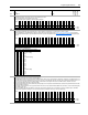
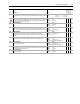
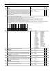
256 Opt 0 Regis Stat
Indicates the registration control status on port 0 of the feedback option card.
• Bit 0 [Armed] indicates the registration latch is armed.
• Bit 1 [Found] indicates the registration event has triggered the latch.
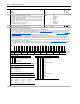
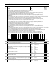
259 Hi Res0 Config
Specifies the configuration options for the Hi-Resolution Encoder Feedback Option.
• Bit 5 [Hi Res Dir] determines the counting direction. If clear, the direction is forward or up. If set, the direction is reverse or down.
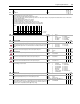
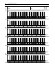
• Bits12 [SmplRate bt0] -15 [SmplRate bt3] configure the sample interval for measuring speed (See Table 259: Encoder Sample Interval). Increasing the
encoder sample interval improves speed measurement near zero speed. Decreasing allows the speed control regulator to perform with high gains at high
speeds.
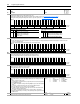
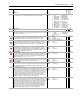
260 Hi Res0 Status
Indicates faults on the Hi-Resolution Encoder Feedback Option.
• Bit 8 [Open Wire] indicates an open wire fault. The feedback option card checks for a pre-determined constant value. If this value is not within tolerances, an
open wire fault is declared. A quadrature check is also done. If an error occurs during the check, the open wire check is aborted. If 3 quadrature errors occur
in succession, the open wire check will complete and the constant value checked again. If this value is not within tolerances, the fault is declared.
• Bit 9 [Power Fail] indicates the failure of the power supply.
• Bit 10 [Diag Fail] indicates the option board failed its power-up diagnostic test. The pattern on the FPGA must be identical to the pattern written from the DSP,
or the board status test will fail.
• Bit 11 [Msg Checksum] indicates a message checksum fault. The check sum associated with the Heidanhain encoder must be correct and acknowledged by
the feedback option card.
• Bit 12 [Time Out Err] indicates a RS-485 time-out fault. This check requires information to be sent from the encoder to the feedback option card within a
specified time. Typical times are about 10 clock cycles before and error is detected. This check is done only at power-up.
No.
Name
Description Values
Linkable
Read-Write
Data Type
Options
Reserved
Reserved
Reserved
Reserved
Reserved
Reserved
Reserved
Reserved
Reserved
Reserved
Reserved
Reserved
Reserved
Reserved
Reserved
Reserved
Reserved
Reserved
Reserved
Reserved
Reserved
Reserved
Reserved
Reserved
Reserved
Reserved
Reserved
Reserved
Reserved
Reserved
Found
Armed
Default00000000000000000000000000000000
Bit 313029282726252423222120191817161514131211109876543210
0 = False
1 = True
Options
Reserved
Reserved
Reserved
Reserved
Reserved
Reserved
Reserved
Reserved
Reserved
Reserved
Reserved
Reserved
Reserved
Reserved
Reserved
Reserved
SmplRate bt3
SmplRate bt2
SmplRate bt1
SmplRate bt0
Reserved
Reserved
Reserved
Reserved
Reserved
SW Reset
Hi Res Dir
Reserved
Reserved
Reserved
Reserved
Reserved
Default00000000010000000000000000000000
Bit 313029282726252423222120191817161514131211109876543210
0 = False
1 = True
Table 259: Encoder Sample Interval
Bit 15 14 13 12 Encoder Sample Interval Settings
00000.5 ms
00010.5 ms (min. setting)
00101.0 ms
00111.5 ms
01002.0 ms (default setting)
01012.5 ms
01103.0 ms
01113.5 ms
10004.0 ms
10014.5 ms
10105.0 ms
10115.5 ms
11006.0 ms (max. setting)
11016.0 ms
11106.0 ms
11116.0 ms
Options
Reserved
Reserved
Reserved
Reserved
Reserved
Reserved
Reserved
Reserved
Reserved
Reserved
Reserved
Reserved
Reserved
Reserved
Reserved
Reserved
Reserved
Reserved
Reserved
Time Out Err
Msg Checksum
Diag Fail
Power Fail
Open Wire
Reserved
Reserved
Reserved
Reserved
Reserved
Reserved
Reserved
Reserved
Default00000000000000000000000000000000
Bit 313029282726252423222120191817161514131211109876543210
0 = False
1 = True