
Owner's manual

3-34 Programming and Parameters
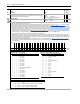
241 Encdr1 Spd Fdbk
Displays the speed feedback from Encoder 1. Calculated from the change of Par 240
[Encdr1 Position] and Par 242 [Encoder1 PPR].
Units:
Default:
Min.Max:
Comm Scale:
RPM
0
-/+14112.0000
Par 4 [Motor NP RPM] = 1.0
Real
242 Encoder1 PPR
Sets the PPR rating of the feedback device connected to the Encoder 1 input.
Units:
Default:
Min/Max:
PPR
1024
10/20000
16-bit
Integer
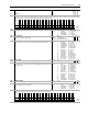
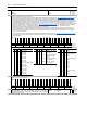
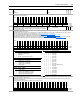
243 Encdr1 Config
Specifies the configuration options for the Encoder 1.
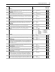
• Bits 0 [Enc Filt bt0], 1 [Enc Filt bt1], 2 [Enc Filt bt2], and 3 [Enc Filt bt3] configure encoder input filter (see Table 243A: Trigger Source Settings). The filter
requires the input signal to be stable for the specified time period. Input transitions within the filter time setting will be ignored.
• Bits 4 [Encdr 4x] and 5 [Encdr A Phs] determine how the encoder channel A and B signals will be interpreted. Typically, both encoder phases A and B are
used so that direction information is available. The Par 240 [Encdr1 Position] counts up for forward rotation and down for reverse rotation. If bit 5 is set, then
the B phase signal is ignored. As a result, the encoder position will only increase, regardless of rotation direction. Bits 4 and 5 together also determine the
number of edges counted per encoder pulse (see Table 243B: Encoder Sample Interval Settings
). "4x" sampling counts both rise and fall of both A and B
encoder phases, hence 4 edges per pulse. In 4x mode, the encoder position will change by four times the encoder pulses per revolution rating (PPR) per
encoder revolution (e.g., it increments the value in Par 240 [Encdr1 Position] by 4096 for one revolution of a 1024 PPR encoder).
• Bit 6 [Encdr Dir] inverts the channel A input, thus reversing the direction of the feedback.
• Bit 9 [Edge Time] configures the method of sampling used by the Velocity Position Loop (VPL). Setting the bit chooses "Edge to Edge" sampling, while
resetting the bit to zero chooses "Simple Difference" sampling. "Simple Difference" sampling calculates speed by examining the difference between pulse
counts over a fixed sample time. "Edge to Edge" sampling adjusts the sample time to synchronize with the position count updates from the daughter card -
improving the accuracy of the speed calculation.
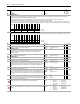
• Bits 12 [SmplRate bt0] through 15 [SmplRate bt3] configure the sample interval for measuring speed (see Table 243C: Channel Interpretation Settings
).
Increasing the encoder sample interval improves speed measurement near zero speed. Decreasing allows the speed control regulator to perform with high
gains at high speeds.
No.
Name
Description Values
Linkable
Read-Write
Data Type
Options
Reserved
Reserved
Reserved
Reserved
Reserved
Reserved
Reserved
Reserved
Reserved
Reserved
Reserved
Reserved
Reserved
Reserved
Reserved
Reserved
SmplRate bt3
SmplRate bt2
SmplRate bt1
SmplRate bt0
Reserved
Reserved
Edge Time
Reserved
Reserved
Encdr Dir
Encdr A Phs
Encdr 4x
Enc Filt bt3
Enc Filt bt2
Enc Filt bt1
Enc Filt bt0
Default00000000000000000010001000011010
Bit 313029282726252423222120191817161514131211109876543210
0 = False
1 = True
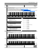
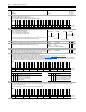
Table 243A: Trigger Source Settings
Bit3210Input Filter Setting
0000Filter disabled
0001100 ns filter
0010200 ns filter
0011300 ns filter
0011300 ns filter
0100400 ns filter
0101500 ns filter
0110600 ns filter
0111700 ns filter
1000800 ns filter (default setting)
1001900 ns filter
10101000 ns filter
10111100 ns filter
11001200 ns filter
11011300 ns filter
11101400 ns filter
11111500 ns filter
Table 243C: Channel Interpretation Settings
Bit 15 14 13 12 Encoder Sample Interval Settings
00000.5 ms
0 0 0 1 0.5 ms (min. setting)
00101.0 ms
00111.5 ms
0 1 0 0 2.0 ms (default setting)
01012.5 ms
01103.0 ms
01113.5 ms
10004.0 ms
10014.5 ms
10105.0 ms
10115.5 ms
1 1 0 0 6.0 ms (max. setting)
11016.0 ms
11106.0 ms
11116.0 ms
Table 243B: Encoder Sample Interval Settings
Bit 5 4 Mult. Directions Comments
0 0 2x fwd/rev Counts rise/fall of phase A, phase B only used to find
direction
0 1 4x fwd/rev Counts rise/fall of both A and B phases (default setting)
1 0 1x fwd only Counts rise of phase A. Phase B ignored.
1 1 2x fwd only Counts rise of phase A. Phase B ignored.