
Owner's manual


Programming and Parameters 3-25
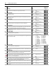
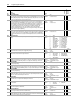
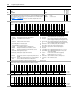
153 Control Options
Set bits to configure the options for operating the drive.
No.
Name
Description Values
Linkable
Read-Write
Data Type
Options
Reserved
Reserved
Reserved
Reserved
Reserved
Tr q Tr i m E n
Reserved
Reserved
Reserved
Reserved
Reserved
Reserved
Reserved
Reserved
Aux Pwr Sply
Auto Tach Sw
Reserved
Reserved
OL ClsLpDsbl
Jog -NoInteg
Iq Delay
Motor Dir
2W CoastStop
3WireControl
Stop Cndt Tq
Stop in Torq
Jog - NoRamp
Jog in Torq
2WCurrLimStp
Sreg LPF 1
SRef Filt En
Bipolar SRef
Default0000000000000000000000010000000 1
Bit 313029282726252423222120191817161514131211109 8 7 6 5 4 3 2 1 0
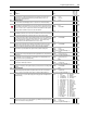
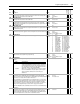
Bit
Name Current Function
0 Bipolar SRef When this bit is enabled a bipolar speed reference is used. In bipolar reference mode, Par 40 [Selected Spd Ref] indicates both the
speed magnitude and the direction: Positive speed reference values (+) = forward direction and negative speed reference values (–)
= reverse direction. When this bit is disabled a unipolar speed reference is used. In unipolar mode, the speed reference is limited to a
minimum value of zero (0). In this case Par
40 [Selected Spd Ref] supplies only the speed magnitude. The direction is determined by
Par 153 [Applied LogicCmd] bits 20 [UniPol Fwd] and 21 [UniPol Rev]. The forward/reverse direction button on the HIM is one
possible source for the [Applied Logic Command] direction bits. The following chart explains the effect that the direction button on the
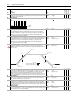
HIM has based on the condition of the “Bipolar SRef” bit:
Bipolar
Reference Controlled By HIM? HIM Direction Button
Enabled Yes Changes the motor direction due to a HIM supplied (+) or (-) command signal
Enabled No Has no effect on motor direction. Direction determined by sign of Par
40 [Selected Spd
Ref].
Disabled Yes Changes the motor direction due to a HIM supplied Forward or Reverse Logic
Command bit.
Disabled No Changes the motor direction due to a HIM supplied Forward or Reverse Logic
Command bit.
In either Bipolar or Unipolar mode, the selected direction can be determined from the sign of Par
41 [Limited Spd Ref]. Positive
values indicate forward rotation and negative values indicate reverse rotation.
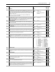
1 SRef Filt En Enables Speed Reference Lead Lag Filter-reset disables
2 Sreg LPF 1 Setting this bit will enable the speed regulator filter as a single order low pass filter
4 Jog in Torq Overrides Par 110 [Spd/Torq ModeSel] setting when jog command received
5 Jog-NoRamp Bypasses the Speed Reference Ramp and S-Curve
6 Stop in Torq Overrides Par 110 [Spd/Torq ModeSel] setting when stopping
8 3WireControl Configures for 3-wire control
11 Iq Delay Enables Torque Current Delay option
12 Jog-NoInteg Configures speed regulator’s integrator to hold when jogging
17 Aux Pwr Sply Enables use of Aux. Power Supply. When set to 1, Main Control Board examines internal 12V DC power to see when energized.
When set to 0, examines voltage of DC Bus. This bit enables Main Control Board and DriveLogix Controller to remain energized
when 3-Ø voltage is de-energized.
0 = False
1 = True