
Owner's manual


3-24 Programming and Parameters
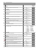
140 FricComp Spd Ref
Supplies a speed input to the Friction Compensation algorithm. This input is normally a
speed reference from a motion planner or ramped speed reference. It will trigger a torque
feed forward response depending on its value.
Units:
Default:
Min/Max:
Comm Scale:
RPM
0.0000
-/+14112.0000
Par 4 [Motor NP RPM] = 1.0
✓✓Real
141 FricComp Setup
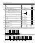
Enter or write a value to configure the friction compensation algorithm. This is a packed
word of 3 digits. Each digit has a possible selection of 10 levels.
• The least significant digit sets the speed threshold in intervals of 0.0005 pu speed.
• The next (middle) digit sets the hysteresis band for the “units” digit in intervals of
0.0005 pu velocity.
• The most significant digit sets the number of time steps from stick to slip, each step is
0.002 sec.
Example: Fsetup = 524 means, 5 time steps between stick and slip, each of 0.002 sec.
duration, 2 counts of hysteresis or 0.001 pu_speed (each count is 0.0005 pu speed), and
4 counts or 0.002 pu_speed is the trigger threshold (each count is 0.0005 pu speed).
Default:
Min/Max:
325
0/999Integer
✓ 16-bit
Integer
142 FricComp Stick
The torque needed to break away from zero speed. By the nature of friction, the break
away sticktion will always be greater than the running friction.
Units:
Default:
Min/Max:
Comm Scale:
P. U .
0.1500
0.0000/8.0000
Motor P.U. Torque
✓✓Real
143 FricComp Slip
The torque level to sustain very low speed – once “break away” has been achieved. By
the nature of friction, viscous friction will always be less than sticktion.
Units:
Default:
Min/Max:
Comm Scale:
P. U .
0.1000
0.0000/8.0000
Motor P.U. Torque
✓✓Real
144 FricComp Rated
The torque needed to a base friction at base motor speed and with no process loading.
The friction compensation algorithm assumes a linear or viscous component of friction
between Par 143 [FricComp Slip] and Par 144 [FricComp Rated].
Units:
Default:
Min/Max:
Comm Scale:
P. U .
0.2000
0.0000/8.0000
Motor P.U. Torque
✓✓Real
145 FricComp TorqAdd
The torque reference output of the Friction Compensation function. A value of 1.0
represents rated torque of the motor.
Units:
Default:
Min/Max:
Comm Scale:
P. U .
0.0000
-/+8.0000
Motor P.U. Torque
Real
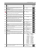
150 Logic State Mach
Indicates the logical state of the drive.
Value 0 - “Stopped” indicates zero speed has been detected and the speed and torque
regulators are disabled.
Default:
Options:
0
0
1
2
3
“Stopped”
“Stopped” 4 “Inertia Test”
“Starting” 5 “MC Diag”
“Running” 6 “Test Done”
“Stopping”
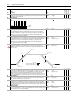
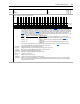
151 Logic Command
The controller-drive interface (as defined by the Controller Communication Format) sets bits to enable and disable various functions and algorithms. Bits that
are changed here are reflected in Par 152 [Applied LogicCmd]. Note: Bits 4 through 9 in Logic Command are NOT recalled from Control EEprom. They will be
cleared upon drive power up or following an EEprom recall operation.
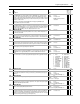
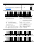
152 Applied LogicCmd
Displays Logic Command that is applied to the Regulators and Control Algorithms within the drive. Logic Commands come from the 32-bit Logic Command
found in a connection with the Logix Controller.
No.
Name
Description Values
Linkable
Read-Write
Data Type
N N N
Units
Hysteresis
Number of
Time Steps
Options
Reserved
Reserved
PositionEnbl
ProcsTrim En
Frict Comp
Inertia Comp
Sys Inert En
Mtr Inert En
PM Offset En
Dir Sel En
Pwr Diag En
MC Atune En
Time Axis En
TachLoss Rst
Spd S Crv En
SpdRamp Dsbl
Default000000000000000 0
Bit 151413121110987654321 0
0 = False
1 = True
Options
Reserved
Reserved
Reserved
Reserved
Reserved
Reserved
Coast Stop
CurrLim Stop
Jog 2
Reserved
UniPol Rev
UniPol Fwd
Clear Fault
Jog 1
Start
Normal Stop
Reserved
Reserved
PositionEnbl
ProcsTrim En
Frict Comp
Inertia Comp
Sys Inert En
Mtr Inert En
PM Offset En
Dir Sel En
Pwr Diag En
MC Atune En
Time Axis En
TachLoss Rst
Spd S Crv En
SpdRamp Dsbl
Default0101100001000010000000000000000 0
Bit 313029282726252423222120191817161514131211109 8 7 6 5 4 3 2 1 0
0 = False
1 = True