
Owner's manual

1-32 Installation/Wiring
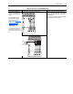
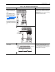
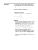
Main Control Board I/O Configuration Settings
Figure 18 Main Control Board Dip Switches
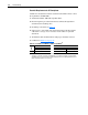
Analog Input Settings
Switch SW1-1 configures the scaling of Analog Input #1. Switch SW1-2
configures the scaling of Analog Input #2. Open the switch for +/-10.0V DC
operation. Close the switch for +/-1.0V DC operation.
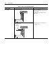
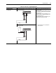
Encoder Input Settings
Dip switch SW2 on the main control board configures the encoder inputs
for 5V DC or 12V DC operation. Switches SW2-2, 4, and 6 are for the
primary encoder. Set these switches to match the encoder output
specifications. Open these switches for 12V DC operation, close them for
5V DC operation.
12
FRONT - TOP VIEW
SIDE VIEW
UP = OPEN = OFF
DOWN = CLOSED= ON
SW1
OPEN
1
FRONT - TOP VIEW
SIDE VIEW
UP = OPEN = OFF
DOWN = CLOSED= ON
SW2
2345678
J6
Pin 3
Pin 2
Pin 1
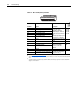
Analog Input #1
Scaling
+/-10.0V DC +/-1.0V DC
SW1-1 Open Closed
Analog Input #2
Scaling
+/-10.0V DC +/-1.0V DC
SW1-2 Open Closed
Primary Encoder SW2-2 SW2-4 SW2-6
5V DC Operation Closed Closed Closed
12V DC Operation Open Open Open
Secondary Encoder SW2-1 SW2-3 SW2-5
5V DC Operation Closed Closed Closed
12V DC Operation Open Open Open
Encoder Power
Supply Voltage
Jumper
Position
5V DC 2-3
12V DC 1-2