
Owner's manual

Installation/Wiring 1-31
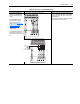
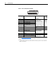
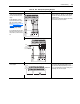
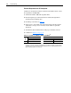
Table 1.Q TB2 - Row B (Bottom) Wiring Examples
Input/Output Connection Example Required Parameter Changes
Secondary Encoder Interface
- Supports 12V DC differential
encoders with internal power
supply.
5V DC differential encoders
require external power supply
and special jumper settings.
Refer to Main Control Board I/O
Configuration Settings on
page 1-32 for external power
supply and jumper settings.
For 5V DC differential encoders
with internal power supply, set
Jumper J6 to positions T2 and
T3.
Secondary Encoder - using internal power supply • Set the value of Parameter 222 [Motor Fdbk
Sel] to a value of 1 - Encoder 1, so the drive will
use this encoder as the primary motor speed
feedback device
• Set the value of Parameter 242 [Encoder1 PPR]
to match the encoder’s resolution
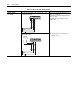
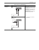
Secondary Encoder - using external power supply
Auxiliary Output - Relay
contact output
Auxiliary Output, Used to Indicate Running • Link Parameter 155 [Logic Status], the source,
to Parameter 841 [Relay Out Data], the sink
• Set Parameter 842 [Relay Out Bit] to a value of
one, so that Parameter 155 [Logic Status] / bit 1
“Running” will control the output.
1312111098721
Power
Common
(Return)
AA
BBZZ
Case Ground
13121110987
Power
Common
(Return)
AA
BBZZ
Case Ground
Shield
Power
Common
(Return)
45
Running
EXTERNAL 24V
POWER SUPPLY
EXTERNAL
24V DC
COMMON
(RETURN)