
Owner's manual

Installation/Wiring 1-21
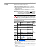
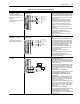
Hard Enable Circuitry
A dedicated hardware enable input is provided for applications that require
the drive to be disabled without software interpretation.
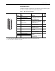
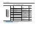
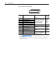
Table 1.J TB1 - Row T (Top) Terminals
Terminal Signal Description
Related
Parameter
T11 Power Supply 24V DC Return (-) Power and common for pre charge
and enable inputs.
(1)
Inputs may
sink or source.
(2)
Rating: 100 mA maximum.
T10 Power Supply 24V DC (+)
T9 Logic Common
T8 Digital Input #1
Default = Precharge
For common DC bus drives. Must
be high, for drive to complete the
pre charge cycle.
Load: 20 mA at 24V DC.
824, 826,
827, 828,
829, 838
T7 Enable Input Must be high for drive to run.
Load: 20 mA at 24V DC.
824, 825
T6 Digital Output #1 24V DC open collector (sinking
logic) output.
Rating: 25 mA maximum.
824, 843,
844
T5 Digital Output #2 24V DC open collector (sinking
logic) output.
Rating: 25 mA maximum.
824, 845,
846
T4 Digital Output Return Return for Digital outputs 1 and 2.
T3 Thermistor Input Used only in FOC2 mode with
approved motor for temperature
adaptation.
Refer to Appendix A, Specifications
for approved motors.
485
T2 Thermistor Input Return
T1 Thermistor Shield
(1)
The drive’s 24V DC power supply supports only on-board digital inputs. Do not use it to power circuits outside of the drive.
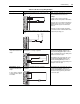
(2)
Refer to wiring examples of sinking and sourcing outputs.
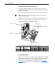
1110
9
8
7
6
5
43T1 2