
Owner's manual

1-14 Installation/Wiring
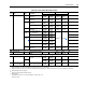
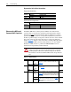
Table 1.E Terminal Block Descriptions
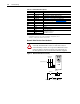
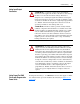
Dynamic Brake Resistor Considerations
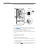
Figure 1.5 External Brake Resistor Circuitry
Terminal Description Notes
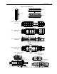
BR1 DC Brake (+) Dynamic Brake Resistor Connection (+)
BR2 DC Brake (–) Dynamic Brake Resistor Connection (–)
DC+ DC Bus (+) DC Input Power or Dynamic Brake Chopper
DC– DC Bus (–) DC Input Power or Dynamic Brake Chopper
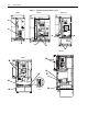
PE PE Ground Refer to Figure 1.4
for location on 3 Frame drives
PS+ Aux + Auxiliary Control Voltage. See Table 1.D on page 1-11
(1)
(1)
Auxiliary power:
UL Installation - 300V DC,
±10%, Non UL Installation - 270-600V DC, ±10%.
1-3 Frame - 40 W, 165 mA, 5 Frame - 80 W, 90 mA
PS- Aux - Auxiliary Control Voltage. See Table 1.D on page 1-11
(1)
Motor Ground Refer to Figure 1.3 for location on 3 Frame drives
U U (T1) To motor
V V (T2) To motor
W W (T3) To motor
R R (L1) AC Line Input Power
Three-Phase = R, S & T
Single-Phase = R & S
S S (L2)
TT (L3)
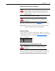
!
ATTENTION: The drive does not offer protection for
externally mounted brake resistors. A risk of fire exists if
external braking resistors are not protected. External resistor
packages must be self-protected from over temperature or a
circuit equivalent to the one shown below must be supplied.
Power On
R (L1)
S (L2)
T (L3)
Power Source DB Resistor Thermostat
Power Off
M
M
(Input Contactor) M
Three-Phase
AC Input