
Owner's manual
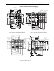
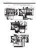
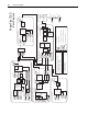
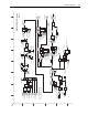

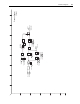
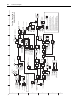
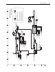
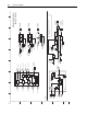

B-8 Control Block Diagrams
Xsync In 1 Xsync Out 1
Xsync Out 2
Xsync In 2
Xsync In 3
Xsync Out 2 Dly
Xsync Out 3 Dly
Xsync Out 3
Xsync Gen Period
SL System Time
Xsync Status
(Sync Pulse)
Act Motor Posit
Act Motor Posit
Position Control
(X Watch 1 En)
(X Watch 1 Dir)
Position Control
(X Watch 2 En)
(X Watch 2 Dir)
PositDetct1 Stpt
PositDetct2 Stpt
In Posit BW
In Posit Dwell
Position Error
Position Status
(Posit Watch1)
Position Status
(Posit Watch2)
Position Status
(In Position)
Position Control (2ms)
Auxiliary / Control
Logic Ctrl State
(Running)
Indexer
(Step)
(Reverse)
Posit Index Ctrl
Posit Index Step
Posit Index Ctrl (Preset)
Posit Ref Sel
(Interpolate)
Motion
Connection
Active
2
0
Latch
Latch
Latch788
790
793
Sync Generator
787
789
791
792
794
795
317
0.5ms
Position Watch 1
Position Watch 2
In Position Detect
763
740 16
740 17
780
741 08
741 09
763
740 18
740 19
781
769
782
783
741 10
Sync Pulse Generator
0.5ms * 2(p787)
0.5ms
786 00
Delay
One
Scan
Delay
One
Scan
785
784
Posit Detct1 In
Posit Detct2 In
Link
Link
&
155 01
152 13
157 03
Logic Ctrl State
(Position En)
740 07
&
OR
741 07
Position Control
(AbsoluteMode)
Posit Ref Sel
(Pt to Pt)
Applied LogicCmd
(PositionEnbl)
151 13
&
1
Pos Reg On (p741 bit 7) needs to be set to activate the
position regulator.
Logic Command
(PositionEnbl)
796 1
796 2
-1
1
X
797
+
796 3
Power up
0
1
OR
0
796 0
799
Index output
Posit Index Ctrl
798
PositIndexPreset
Auxiliary
Control
1
2
3
4
5
6
BA
D
C
FE HG
I
[6C5] & [6G3] & [7G4]
(Enable)
Position Status
(Regulator On)
&
1
8