
Owner's manual

4-2 Troubleshooting
LED Indications
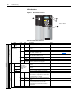
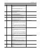
Figure 4.1 Drive Status Indicators
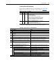
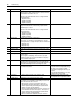
Table 4.A Drive Status Indicators
DRIVE
DRIVE
SYNCHLINK
ENABLE
3
2
1
4
Frame 1 Shown
# Name Color State Description Action
DRIVE
Power Structure
➊
PWR
(Power)
Green Steady Illuminates when power is applied to the drive. No action - no faults present
➋
STS (Status)
Green Flashing Drive ready, but not running & no faults are
present.
No action - no faults present
Steady Drive running, no faults are present. No action - no faults present
Yellow Flashing A type 2 (non-configurable) alarm condition
exists, drive continues to run.
A run inhibit exists. Refer to Table 4.B
Steady A type 1 (user configurable) alarm condition
exists, but drive continues to run.
Red Flashing A fault has occurred. Refer to Table for faults.
Steady A non-resettable fault has occurred.
Red /
Ye l l o w
Flashing
Alternately
The drive is in flash recovery mode. The only
operation permitted is flash upgrade.
Complete Flash Upgrade
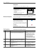
Control Assembly
Communications
➌
PORT
Refer to the
Communication
Adapter User
Manual
Status of DPI port internal communications (if
present).
MOD Status of communications module (when
installed).
NET A Status of network (if connected).
NET B Status of secondary network (if connected).
Control
➍
SYNCHLINK Green Steady • The module is configured as the time keeper
or
• The module is configured as a follower and
synchronization is complete.
Green Flashing The follower(s) are not configured with the time
keeper.
Red Flashing • The module is configured as a time master
on SynchLink and has received time
information from another time master on
SynchLink.
ENABLE Green On The drive’s enable input is high.