
Owner's manual


3-92 Programming and Parameters
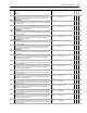
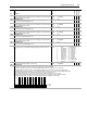
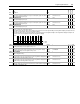
1229 SL Error Status
Indicates presence of SynchLink faults. This data is visible on the SynchLink diagnostics tab of the Peer Communication window.
• Bit 0 [Sync Loss] indicates SynchLink communication has failed, after it had been established
• Bit 1 [Rx Loss] indicates the receive port is not receiving data, and the receive port configuration is set to receive data
• Bit 2 [Many BOF Err] indicates the number of Beginning Of Frame (BOF) errors exceeds limit set by Par 1235 [SL BOF Err Limit]
• Bit 3 [Many CRC Err] indicates the number of Cyclic Redundancy Check (CRC) errors exceeds limit set by Par 1234 [SL CRC Err Limit]
• Bit 4 [Pckg Msg Err] indicates the received package sequence number has not matched for 1.0S
• Bit 5 [CommForm Err] indicates the format of received data does not match the configuration of the receive port
• Bit 6 [Sys Rev Err] indicates the system revision in the received data does not match the value of Par 1001 [SynchLink Rev]
• Bit 7 [Mult TKeeper] indicates more than one node on the SynchLink system is configured as a time keeper
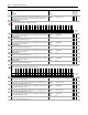
1230 SL CRC Err Accum
Displays the total accumulated number of CRC errors. Clearing a CRC fault resets this
accumulator. This data is visible on the SynchLink diagnostics tab of the Peer
Communication window.
Default:
Min/Max:
0
0/4294967296
32-bit
Integer
1231 SL CRC Error
Displays the number of CRC errors that occurred during the last test (last 8 mS). This
data is visible on the SynchLink diagnostics tab of the Peer Communication window.
Default:
Min/Max:
0
0/4294967296
32-bit
Integer
1232 SL BOF Err Accum
Displays the total accumulated number of BOF errors. Clearing a BOF fault resets this
accumulator. This data is visible on the SynchLink diagnostics tab of the Peer
Communication window.
Default:
Min/Max:
0
0/4294967296r
32-bit
Integer
1233 SL BOF Error
Displays the number of BOF errors that occurred during the last test (last 8 mS). This data
is visible on the SynchLink diagnostics tab of the Peer Communication window.
Default:
Min/Max:
0
0/4294967296
32-bit
Integer
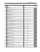
1234 SL CRC Err Limit
The number of CRC errors per test (per 8 mS) allowed before the drive declares a
SynchLink CRC Error exception event. Set this limit on the SynchLink diagnostics tab of
the Peer Communication window.
Default:
Min/Max:
2
0/256
32-bit
Integer
1235 SL BOF Err Limit
The number of BOF errors per test (per 8 mS) allowed before the drive declares a
SynchLink BOF Error exception event. Set this limit on the SynchLink diagnostics tab of
the Peer Communication window.
Default:
Min/Max:
2
0/256
32-bit
Integer
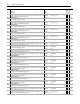
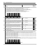
1250 Trend Control
Set bits to configure the Data Trend function:
• Bit 0 [Enbl Collect] - Trend data collection begins on the rising edge of this bit and continues until either this bit is set low or the trend data has been completely
collected. This bit should be cleared following either the 'Triggered' status or 'Complete' status (bit 1 and 2, respectively, in Par 1251 [Trend Status]) in order to
complete the trend sequence. This bit can also be cleared at any time to force the trend data sampling to stop and set the 'Complete' status bit.
• Setting bit 1 [In1 Real] - specifies the Real data type for Trend Input 1. The source for Real data is Par 1265 [Trend In1 Real]. Clearing the bit specifies the Integer
data type. The source for Integer data is Par 1264 [Trend In1 Int].
• Setting bit 2 [In2 Real] - specifies the Real data type for Trend Input 2. The source for Real data is Par 1267 [Trend In2 Real]. Clearing the bit specifies the Integer
data type. The source for Integer data is Par 1266 [Trend In2 Int].
• Setting bit 3 [In3 Real] - specifies the Real data type for Trend Input 3. The source for Real data is Par 1269 [Trend In3 Real]. Clearing the bit specifies the Integer
data type. The source for Integer data is Par 1268 [Trend In3 Int].
• Setting bit 4 [In4 Real] - specifies the Real data type for Trend Input 4. The source for Real data is Par 1271 [Trend In4 Real]. Clearing the bit specifies the Integer
data type. The source for Integer data is Par 1270 [Trend In4 Int].
• Setting bit 15 [Auto Output] causes the trend output parameters to automatically cycle through the entire trend buffer at the rate specified in Par 1253 [Trend Rate].
Typically, you link the output to an analog output for display on an oscilloscope.
• Auto output is accomplished by writing to Par 1283 [TrendBuffPointer]. Clearing this bit requires manual selection of Par 1283 [TrendBuffPointer] to view the trend
buffer contents.
No.
Name
Description Value
Linkable
Read-Write
Data Type
Options
Reserved
Reserved
Reserved
Reserved
Reserved
Reserved
Reserved
Reserved
Mult TKeeper
Sys Rev Err
CommForm Err
Pckg Msg Err
Many CRC Err
Many BOF Err
Rx Loss
Sync Loss
Default0000000000000000
Bit 1514131211109876543210
0 = False
1 = True
Options
Auto Output
Reserved
Reserved
Reserved
Reserved
Reserved
Reserved
Reserved
Reserved
Reserved
Reserved
In 4 Real
In 3 Real
In 2 Real
In 1 Real
Enbl Collect
Default0000000000000000
Bit 1514131211109876543210
0 = False
1 = True