
Owner's manual

Programming and Parameters 3-81
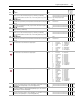
944 Positin ErrCnfg
Position error for a Motion Servo axis has exceeded the configured limit.
• 0 “Ignore” - configures the drive to continue running, as normal, when this event occurs
• 1 “Alarm” - configures the drive to continue running and set the appropriate alarm bit
when this event occurs
• 2 “FltCoastStop” - configures the drive to perform a coast stop and set the appropriate
fault bit, in response this event.
• 3 “Flt RampStop” - configures the drive to perform a ramp stop and set the appropriate
fault bit, in response this event.
• 4 “FltCurLimStp” - configures the drive to perform a current-limit stop and set the
appropriate fault bit, in response this event.
Default:
Options:
1
0
1
2
3
4
“Alarm”
“Ignore”
“Alarm”
“FltCoastStop”
“Flt RampStop”
“FltCurLimStp”
1000
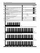
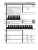
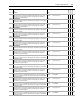
SL Node Cnfg
Set bits to configure the SynchLink node.
• Setting bit 0 [Time Keeper] configures the local node as the Time Master.
• Setting bit 2 [Sync Now] configures the node to synchronize with the Time Master immediately (1-2S per node) on power-up or recovery. If you do not set bit 2, the
node will stay in the fast mode, taking up to 36S per node to synchronize on power-up or recovery.
1001 SynchLink Rev
Indicates the current revision of the local SynchLink Programmable Logic Firmware.
Default:
Min/Max:
Comm Scale:
0.1
0.1/999.9
x 10
16-bit
Integer
1002 SL System Rev
Indicates the system revision of the SynchLink network. To be compatible on the network,
all nodes must have the same major revision.
Default:
Min/Max:
Comm Scale:
0.001
0.001/999.999
x 1000
32-bit
Integer
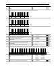
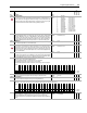
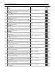
1003 Interp SynchInput
Bit 0 [Sync Pulse] of this parameter is used as the synchronization pulse for he Interpolator. This parameter is linked to Par 919 [Motn Posit Sync] for a Motion Servo
axis. It is linked to Par 786 [Xsync Status] for a SynchLink application.
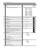
1010 SL Rx Comm Frmt
Defines the node's communication format for receiving SynchLink data. This determines
the number of axis data, direct data and buffered data words received. Configure the
format by using the Peer Communication window in the DriveExecutive programming
software.
1011 SL Rx DirectSel0
Determines the destination for the data received at word 0 of direct received data.
Configure the selection by using the Peer Communication window in the DriveExecutive
programming software.
Default:
Options:
0
0
1
2
3
4
5
“No Data”
“No Data” 6 “Reserved”
“SL Multiply” 7 “Reserved”
“Event P0” 8 “Event Opt0”
“Reserved” 9 “Reserved”
“Reserved” 10 “Event Status”
“Reserved”
1012 SL Rx DirectSel1
Determines the destination for the data received at word 1 of direct received data.
Configure the selection by using the Peer Communication window in the DriveExecutive
programming software.
Default:
Options:
0
0
1
2
3
4
5
“No Data”
“No Data” 6 “Reserved”
“SL Multiply” 7 “Reserved”
“Event P0” 8 “Event Opt0”
“Reserved” 9 “Reserved”
“Reserved” 10 “Event Status”
“Reserved”
No.
Name
Description Values
Linkable
Read-Write
Data Type
Options
Reserved
Reserved
Reserved
Reserved
Reserved
Reserved
Reserved
Reserved
Reserved
Reserved
Reserved
Reserved
Reserved
Sync Now
Reserved
Time Keeper
Default0000000000000000
Bit 1514131211109876543210
0 = False
1 = True
Options
Reserved
Reserved
Reserved
Reserved
Reserved
Reserved
Reserved
Reserved
Reserved
Reserved
Reserved
Reserved
Reserved
Reserved
Reserved
Reserved
Reserved
Reserved
Reserved
Reserved
Reserved
Reserved
Reserved
Reserved
Reserved
Reserved
Reserved
Reserved
Reserved
Reserved
Reserved
Sync Pulse
Default00000000000000000000000000000000
Bit 313029282726252423222120191817161514131211109 8 7 6 5 4 3 2 1 0
0 = False
1 = True
Value (A)xis (D)irect (B)uffered
Options 0 0 0 0
6124
70218
9048
16144
170418