
Owner's manual

3-80 Programming and Parameters
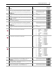
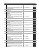
922 Motn TP Select
Selector for diagnostic testpoint relating to Motion functionality.
0
0
1
2
3
4
5
6
7
8
9
10
11
12
13
14
15
“ServoAxisCnfg”
“ServoAxisCnfg” 16 ““CST Upper”
“ServoAxisUnwd” 17 “Reserved”
“Marker Dist” 18 “Reserved”
“HomeEvent X” 19 “I/O Rx Seq#”
“Watch Posit” 20 “I/O Rx Msg#”
“Home Posit” 21 “I/O Tx Msg#
“SrvoMRP Ofst” 22 “Syn Rx Seq#”
“SrvoAct Ofst” 23 “Syn RxMsg#”
“PositRegis 1” 24 “Syn Tx Msg#”
“PositRegis 2” 25 “Evt Rx Seq#”
“FdbkAxisCnfg” 26 “Evt Rx Msg#”
“FdbkAxisUnwd” 27 “Evt Rx Tx Msg#”
“FdbkMRP Ofst” 28 “Asy Rx Seq#”
“FdbkAct Ofst” 29 “Asy Rx Msg#”
“TimeEvntStat” 30 “Asy Tx Msg#”
“CST Lower” 31 “Reset Msg#”
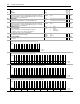
923 Motn TP Value
Data for diagnostic testpoint relating to Motion functionality.
Default:
Min/Max:
0
-/+2147483648
DWord
924 Motn RotaryCmmd
Position command input from the Motion Planner to the Servo axis when configured in
rotary mode.
Default:
Min/Max:
0
-/+2147483648
DWord
925 MotnUnwdTurnCmmd
Position unwind turns command input from the Motion Planner to the Servo axis when
configured in rotary mode.
Default:
Min/Max:
0
-/+32768
Word
926 SrvoAxis RotFdbk
Position feedback output to the Motion Planner for the Servo axis when configured in
rotary mode.
Default:
Min/Max:
0
-/+2147483648
DWord
927 SrvoAxisUnwdFdbk
Potion unwind feedback output to the Motion Planner for the Servo axis when configured
in rotary mode.
Default:
Min/Max:
0
-/+32768
Word
928 FdbkAxis RotFdbk
Position feedback output to the Motion Planner for the Feedback Only axis when
configured in rotary mode.
Default:
Min/Max:
0
-/+2147483648
DWord
929 FdbkAxisUnwdFdbk
Position unwind feedback output to the Motion Planner for the Feedback Only axis when
configured in rotary mode.
Default:
Min/Max:
0
-/+32768
Word
930 MotnCnfgErrParam
Indicates a parameter that is not configured properly for a motion connection to be
accepted. Parameter could either have a wrong value or an incorrect link. When bit 0
[Config OK] of Par 907 [Motn Cnct Status} is set, then this parameter contains the
parameter number of an incorrectly configured parameter. If more than one parameter is
incorrectly configured, they are displayed after others are fixed. If there are no
configuration problems relating to Motion, then this parameter contains the value of zero
and bit 0 [Config OK] of Par 907 is cleared.
Default:
Min/Max:
0
0/65535
Word
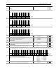
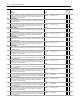
940
941
+Sft OvrTrvlCnfg
-Sft OvrTrvlCnfg
Synchronization input to the Interpolator has been lost or has become excessively
irregular.
• 0 “Ignore” - configures the drive to continue running, as normal, when this event occurs
• 1 “Alarm” - configures the drive to continue running and set the appropriate alarm bit
when this event occurs
• 2 “FltCoastStop” - configures the drive to perform a coast stop and set the appropriate
fault bit, in response this event.
• 3 “Flt RampStop” - configures the drive to perform a ramp stop and set the appropriate
fault bit, in response this event.
• 4 “FltCurLimStp” - configures the drive to perform a current-limit stop and set the
appropriate fault bit, in response this event.
Default:
Options:
1
0
1
2
3
4
“Alarm”
“Ignore”
“Alarm”
“FltCoastStop”
“Flt RampStop”
“FltCurLimStp”
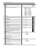
942
943
+Hrd OvrTrvlCnfg
-Hrd OvrTrvlCnfg
Active signal from a digital input that is configured as a positive hard overtravel input.
• 0 “Ignore” - configures the drive to continue running, as normal, when this event occurs
• 1 “Alarm” - configures the drive to continue running and set the appropriate alarm bit
when this event occurs
• 2 “FltCoastStop” - configures the drive to perform a coast stop and set the appropriate
fault bit, in response this event.
• 3 “Flt RampStop” - configures the drive to perform a ramp stop and set the appropriate
fault bit, in response this event.
• 4 “FltCurLimStp” - configures the drive to perform a current-limit stop and set the
appropriate fault bit, in response this event.
Default:
Options:
1
0
1
2
3
4
“Alarm”
“Ignore”
“Alarm”
“FltCoastStop”
“Flt RampStop”
“FltCurLimStp”
No.
Name
Description Values
Linkable
Read-Write
Data Type