
Owner's manual

3-76 Programming and Parameters
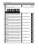
No.
Name
Description Values
Linkable
Read-Write
Data Type
814 AnlgOut1 Integer
Link this parameter to an integer source parameter and that source will control Analog
Output 1.
Default:
Min/Max:
0
-/+2147483648
✓✓32-bit
Integer
815 Anlg Out1 Real
Link this parameter to a real (floating point) source parameter and that source will control
Analog Output 1.
Default:
Min/Max:
0.0000
-/+2200000000.0000.0000
✓✓Real
816 Anlg Out1 Volts
Displays the voltage reference for Analog Output 1, before the digital to analog
conversion.
Units:
Default:
Min/Max:
Volt
0.0000
-/+10.0000
Real
817 Anlg Out1 Scale
Scales the range of the source parameter to the range of Analog Output 1. Par 814
[AnlgOut1 Integer] or Par 815 [Anlg Out1 Real] is multiplied by this number after the limit
function.
Units:
Default:
Min/Max:
/1v
0.0000
-/+2200000000.0000
v ✓ Real
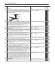
818 Anlg Out1 Zero
Applies an offset to the scaled value of the Analog Output 1 function. This parameter is
summed with the output of the scaling block. This sum produces Par 816 [Anlg Out1
Volts]. Typically this value corresponds to 0V for Analog Output 1.
Units:
Default:
Min/Max:
Volt
0.0000
-/+20.0000
✓✓Real
819 AnlgOut2 Integer
Link this parameter to an integer source parameter and that source will control Analog
Output 2.
Default:
Min/Max:
0
-/+2147483648
✓✓Real
820 Anlg Out2 Real
Link this parameter to a real (floating point) source parameter and that source will control
Analog Output 2.
Default:
Min/Max:
0.0000
-/+2200000000.0000
✓✓Real
821 Anlg Out2 Volts
Displays the voltage reference for Analog Output 2, before the digital to analog
conversion.
Units:
Default:
Min/Max:
Volt
0.0000
-/+10.0000
Real
822 Anlg Out2 Scale
Scales the range of the source parameter to the range of Analog Output 2. Par 819
[AnlgOut2 Integer] or Par 820 [Anlg Out2 Real] is multiplied by this number after the limit
function.
Units:
Default:
Min/Max:
/1v
0.0000
-/+2200000000.0000
✓✓Real
823 Anlg Out2 Zero
Applies an offset to the scaled value of the Analog Output 2 function. This parameter is
summed with the output of the scaling block. This sum produces Par 821 [Anlg Out2
Volts]. Typically this value corresponds to 0V for Analog Output 2.
Units:
Default:
Min/Max:
Volt
0.0000
-/+20.0000
✓✓Real
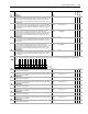
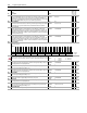
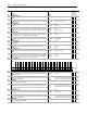
824 Local I/O Status
Displays the status of the local I/O.
825 En In Debounce
Sets the value of the debounce filter for the Enable input. The filter requires the input
signal to be stable for the specified time period. Input transitions within the filter time
setting will be ignored.
Units:
Default:
Min/Max:
mSec
8.0000/0.0000
15.5000
✓✓Real
826 DigIn1 Data
Sets the value of Par 828 [DigIn1 User Data], except for the bit controlled by bit 1 [DigIn 1]
of Par 824 [Local I/O Status].
Default:
Min
Max:
00000000000000000000000000000000
00000000000000000000000000000000
11111111111111111111111111111111
✓✓32-bit
Boolean
827 DigIn1 Bit
Selects the bit, in Par 828 [DigIn1 User Data], which is controlled by bit controlled by bit 1
[DigIn 1] of Par 824 [Local I/O Status].
Default:
Min/Max:
0
-32/31
✓✓16-bit
Integer
828 DigIn1 User Data
Provides a source of data controlled by bit 1 [DigIn 1] of Par 824 [Local I/O Status].
Link to a Read-Write parameter and enter a value of 13 in Par 838 [DigIn1 Sel] to activate
this function.
Default:
Min:
Max:
00000000000000000000000000000000
00000000000000000000000000000000
11111111111111111111111111111111
32-bit
Boolean
829 DigIn1 Debounce
Sets the value of the debounce filter for Digital Input 1. The filter requires the input signal
to be stable for the specified time period. Input transitions within the filter time setting will
be ignored.
Units:
Default:
Min/Max:
mSec
8.0000
0.0000/15.5000
✓✓Real
830 DigIn2 Data
Sets the value of Par 832 [DigIn2 User Data], except for the bit controlled by bit 2 [DigIn 2]
of Par 824 [Local I/O Status].
Default:
Min:
Max:
00000000000000000000000000000000
00000000000000000000000000000000
11111111111111111111111111111111
✓✓32-bit
Boolean
831 DigIn2 Bit
Selects the bit, in Par 832 [DigIn2 User Data], which is controlled by bit controlled by bit 2
[DigIn 2] of Par 824 [Local I/O Status].
Default:
Min/Max:
0
-32/31
✓✓16-bit
Integer
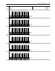
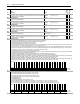
Options
Reserved
Reserved
Reserved
Reserved
Reserved
Reserved
Reserved
Reserved
Reserved
VPL Gate Ena
Watch Dog
VP TP2 Out
VP TP1 Out
Aux Out 2
Aux Out 1
Output Relay
Reserved
Reserved
Reserved
Reserved
Reserved
Reserved
Reserved
Reserved
Reserved
Reserved
Reserved
LogixPresent
DigIn 3
DigIn 2
DigIn 1
Enable In
Default00000000000000000000000000000000
Bit 313029282726252423222120191817161514131211109876543210
0 = False
1 = True