User Manual PowerFlex 700S High Performance AC Drive Phase I Control Firmware Versions1.xx-2.
Important User Information Read this document and the documents listed in the additional resources section about installation, configuration, and operation of this equipment before you install, configure, operate, or maintain this product. Users are required to familiarize themselves with installation and wiring instructions in addition to requirements of all applicable codes, laws, and standards.
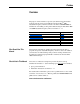
Summary of Changes This manual contains new and updated information. New and Updated Information This table contains the changes made to this revision. Topic Page Updated the front and inside front covers. – Updated the Electronic Motor Overload Protection statement. A-3 Updated the Drive Fusing and Circuit Breaker information and Protection Device tables. A-6…A-16 Updated the back cover.
soc-2 Notes:
Table of Contents Important User Information . . . . . . . . . . . . . . . . . . . . . . . . . . . . . . . . . . . . . . . . . . . . . . . 1-2 Summary of Changes Manual Updates . . . . . . . . . . . . . . . . . . . . . . . . . . . . . . . . . . . . . . . . . . . . . . . . . . . . . . . . . i-1 Preface Overview Who Should Use This Manual . . . . . . . . . . . . . . . . . . . . . . . . . . . . . . . . . . . . . . . . . . . . . What Is Not In This Manual . . . . . . . . . . . . . . . . . . . . . . . . . .
ii Table of Contents Chapter 1 Installation/Wiring Chapter Objectives. . . . . . . . . . . . . . . . . . . . . . . . . . . . . . . . . . . . . . . . . . . . . . . . . . . . . . . 1-1 Opening the Cover . . . . . . . . . . . . . . . . . . . . . . . . . . . . . . . . . . . . . . . . . . . . . . . . . . . . . . . 1-2 Mounting Clearances . . . . . . . . . . . . . . . . . . . . . . . . . . . . . . . . . . . . . . . . . . . . . . . . . . . . . 1-2 Operating Temperatures. . . . . . . . . . . . . . . . . . . . .
Table of Contents Chapter 3 iii Programming and Parameters About Parameters . . . . . . . . . . . . . . . . . . . . . . . . . . . . . . . . . . . . . . . . . . . . . . . . . . . . . . . 3-1 How Parameters are Organized . . . . . . . . . . . . . . . . . . . . . . . . . . . . . . . . . . . . . . . . . . . . . 3-3 Parameter Data in Linear List Format. . . . . . . . . . . . . . . . . . . . . . . . . . . . . . . . . . . . . . . 3-16 Parameter Cross Reference By Name . . . . . . . . . . . . . . . . . . . . . .
iv Table of Contents Appendix D HIM Overview External and Internal Connections. . . . . . . . . . . . . . . . . . . . . . . . . . . . . . . . . . . . . . . . . . . LCD Display Elements . . . . . . . . . . . . . . . . . . . . . . . . . . . . . . . . . . . . . . . . . . . . . . . . . . . ALT Functions . . . . . . . . . . . . . . . . . . . . . . . . . . . . . . . . . . . . . . . . . . . . . . . . . . . . . . . . . . Removing/Installing the HIM . . . . . . . . . . . . . . . . . . . . . . . . . . . . . . . .
Preface Overview The purpose of this manual is to provide you with the basic information needed to install, start-up and troubleshoot the PowerFlex® 700S Adjustable Frequency AC Drive, Frames 1-6. Refer to PFLEX-IN006 for information on installing, starting and troubleshooting the PowerFlex 700S and 700H Adjustable Frequency Drives for Frames 9 - 11.
p-2 Overview Recommended Documentation The following publications provide general drive information. Title Wiring and Grounding for PWM AC Drives Safety Guidelines for the Application, Installation and Maintenance of Solid State Control A Global Reference Guide for Reading Schematic Diagrams Guarding Against Electrostatic Damage Publication DRIVES-IN001 Available… SGI-1.1 www.rockwellautomation.com/ literature 100-2.10 8000-4.5.
Overview Title Installation Instructions - DriveLogix Controller for PowerFlex 700S Drives Logix5000 Controllers General Instructions ControlNet Daughtercard Installation Instructions ControlNet Daughtercard Installation Instructions Logix5000 Controllers Process Control and Drives Instructions RSLogix 5000 Getting Results RSNetworx for ControlNet Getting Results RSLinx Getting Results Guide Publication 20D-IN003 1756-RM003 1788-IN002 1788-IN005 1756-RM006 p-3 Available… www.rockwellautomation.
p-4 Overview General Precautions Class 1 LED Product ! ! ! ! ! ! ! ! ATTENTION: Hazard of permanent eye damage exists when using optical transmission equipment. This product emits intense light and invisible radiation. Do not look into module ports or fiber optic cable connectors. ATTENTION: This drive contains ESD (Electrostatic Discharge) sensitive parts and assemblies. Static control precautions are required when installing, testing, servicing or repairing this assembly.
Overview p-5 Catalog Number Explanation Important: This table is not intended for ordering. For a full list of current options refer to publication 20D-PL001, PowerFlex 700S/700S DriveLogix USA Price List.
p-6 Overview Catalog Number Explanation, Cont’d c5 h k ND Rating Brake Resistor Control Options 690V, 50 Hz Input ♣ Code w/Resistor Code Amps Hp Y Yes 9 052 52 45 N No 060 60 55 082 82 75 098 98 90 119 119 110 142 142 132 ♣ CE Certification testing has not been performed on 600V class drives.
Chapter 1 Installation/Wiring Chapter Objectives This chapter provides the information needed to mount and wire the PowerFlex 700S AC drive for Frames 1 - 6. For installation instructions for the PowerFlex 700S AC drive for Frames 9 - 12, refer to PFLEX-IN006.
1-2 Installation/Wiring Opening the Cover B Frames 1-6 DRIVE DRIVE B C 9 4 5 1 2 3 . 0 +/- Sel Opening Control Assembly A Auto / Man 8 Exit Esc SYNCHLINK Step Lang 7 S.M.A.R.T. ENABLE Alt Description Loosen captive screw. Push down on cover. Pull cover away from assembly. Exp 6 Remove Jog Param # Frames 1-4 Locate the slot in the upper left corner. Slide the locking tab up and swing the cover open.
Installation/Wiring 1-3 Operating Temperatures PowerFlex 700S drives are designed to operate in surrounding air temperature of 0° to 40° C. To operate the drive in installations with surrounding air temperature between 41° and 50° C, remove the adhesive label affixed to the top of the drive enclosure. Table 1.A Acceptable Surrounding Air Temperature & Required Actions Drive Catalog Number All Except 20BC072 20BC072 (1) Required Action . . .
1-4 Installation/Wiring Input Power Conditioning Certain events on the power system supplying a drive can cause component damage or shortened product life. These conditions are divided into 2 basic categories: 1. All Drives – The power system has power factor correction capacitors switched in and out of the system, either by the user or by the power company. – The power source has intermittent voltage spikes in excess of 6000 volts.
Installation/Wiring 1-5 Figure 1.1 Typical Grounding R (L1) S (L2) T (L3) PE U (T1) V (T2) W (T3) DC + DC – BR1 BR2 Required Input Fusing Required Branch Circuit Disconnect Shield Termination - SHLD The Shield terminal (see Figure 1.3 on page 1-12) provides a grounding point for the motor cable shield. It must be connected to an earth ground by a separate continuous lead. The motor cable shield should be connected to this terminal on the drive (drive end) and the motor frame (motor end).
1-6 Installation/Wiring Power Wiring Power Cable Types Acceptable for 200-600 Volt Installations ! ATTENTION: National Codes and standards (NEC, BSI etc.) and local codes outline provisions for safely installing electrical equipment. Installation must comply with specifications regarding wire types, conductor sizes, branch circuit protection and disconnect devices. Failure to do so may result in personal injury and/or equipment damage. A variety of cable types are acceptable for drive installations.
Installation/Wiring 1-7 A good example of recommended cable is Belden® 295xx (xx determines gauge). This cable has 4 XLPE insulated conductors with a 100% coverage foil and an 85% coverage copper braided shield (with drain wire) surrounded by a PVC jacket. Other types of shielded cable are available, but the selection of these types may limit the allowable cable length. Particularly, some of the newer cables twist 4 conductors of THHN wire and wrap them tightly with a foil shield.
1-8 Installation/Wiring Motor Cable Lengths Typically, motor lead lengths less than 30 meters (100 feet) are acceptable. Motor lead lengths of 30 meters (100 feet) to 246 meters (800 feet) require shielded cable. If your application dictates longer lengths, refer to publication 20D-TD001, Technical Data - PowerFlex 700S Drives, for details. Power Terminal Block Figure 1.3 shows the typical location of the Power Terminal Block in Frame 1 drives.
Installation/Wiring 1-9 Replace the cover when wiring is complete. ! ATTENTION: Removing the access panel/cover exposes dangerous voltages on the terminals and negates the enclosure type rating. Replace the access panel/cover when service is complete. Failure to comply may result in personal injury or equipment damage. AC Input Phase Selection (Frames 5 & 6 Only) ! ATTENTION: To avoid a shock hazard, ensure that all power to the drive has been removed before performing the following.
1-10 Installation/Wiring Figure 1.2 Frames 5 & 6 Jumper and Transformer Locations (Frame 5 shown) Phase Selection Jumper 3-PH 1-PH LINE TYPE Optional Communications Module SPARE 1 SPARE 2 WIRE RANGE: 22-10 AWG (0.5-4 MM2) TORQUE: 5.3 IN-LB (0.6 N-M) STRIP LENGTH: 0.35 IN (9 MM) 9 17 GROUND TERMINAL RATINGS (PE) Fan Voltage 300 VDC EXT PWR SPLY TERM (PS+, PS-) POWER TERMINAL RATINGS WIRE RANGE: 14-1/0 AWG (2.5-35 MM2) TORQUE: 32 IN-LB (3.6 N-M) STRIP LENGTH: 0.
Installation/Wiring 1-11 Table 1.D Power Terminal Block Specifications Wire Size Range(1) Torque Maximum Minimum Maximum Recommended 4.0 mm2 (10 AWG) 2 10.0 mm2 (6 AWG) 3 25.0 mm2 (3 AWG) 10.0 mm2 (6 AWG) 4 Input power and motor 35.0 mm2 connections (1/0 AWG) 5 R, S, T, BR1, BR2, DC+, 50.0 mm2 (75 HP)(3) DC-, U, V and W (1/0 AWG) PE 50.0 mm2 (1/0 AWG) 5 R, S, T, DC+, DC-, U, V and 70.0 mm2 (100 HP)(3) W (2/0 AWG) BR1, BR2 50.0 mm2 (1/0 AWG) PE 50.0 mm2 (1/0 AWG) 6 Input power and motor 120.
1-12 Installation/Wiring Figure 1.3 Typical Power Terminal Block Location Frame 2 Frame 1 Frame 3 & 4 ➌ ! Optional Communications Module DANGER Use 75C Wire Only ➊ Optional Communications Module #10-#14 AWG Torque to 7 in-lbs PE B BR1 BR2 PE A DC+ POWER PE 75C Cu Wire 6 AWG [10MM2] Max. CONTROL WIRE STRIP DC– 12 IN. LBS. 1.4 N-M } TORQUE U/T1 PE R/L1 S/L2 T/L3 T/L3 SHLD ➌ WIRE STRIP BR1 BR2 ➌ AUX IN+ AUX OUT– R/L1 S/L2 75C Cu Wire 6 AWG [10MM2] Max. 12 IN. LBS. 1.
Installation/Wiring Figure 1.
1-14 Installation/Wiring Table 1.E Terminal Block Descriptions Terminal BR1 BR2 DC+ DC– PE PS+ PSU V W R S T (1) Description DC Brake (+) DC Brake (–) DC Bus (+) DC Bus (–) PE Ground Aux + Aux Motor Ground U (T1) V (T2) W (T3) R (L1) S (L2) T (L3) Notes Dynamic Brake Resistor Connection (+) Dynamic Brake Resistor Connection (–) DC Input Power or Dynamic Brake Chopper DC Input Power or Dynamic Brake Chopper Refer to Figure 1.4 for location on 3 Frame drives Auxiliary Control Voltage. See Table 1.
Installation/Wiring Using Input/Output Contactors ! ! ! Using PowerFlex 700S Drives with Regenerative Power Units 1-15 ATTENTION: A contactor or other device that routinely disconnects and reapplies the AC line to the drive to start and stop the motor can cause drive hardware damage. The drive is designed to use control input signals that will start and stop the motor.
1-16 Installation/Wiring Regenerative Unit to Drive Connections Regenerative Brake Mode Frame(s) 1-4 5&6 Terminals 1336 Regen DC+ & DCDC+ & DC- PowerFlex 700S BR1 & DCDC+ & DC- Regenerative Bus Supply Mode Frame(s) 1-4 5&6 Disconnecting MOVs and Common Mode Capacitors Terminals 1336 Regen DC+ & DCDC+ & DC- PowerFlex 700S DC+ & DCDC+ & DC- of the Common Bus Drives PowerFlex 700S drives contain protective MOVs and common mode capacitors that are referenced to ground.
Installation/Wiring Frames Jumper 6 Wire ! Component Common Mode Capacitors MOV’s Input Filter Capacitors Jumper Location Remove the wire guard from the Power Terminal Block. Disconnect the three green/yellow wires from the two “PE” terminals shown in Figure 1.4. Insulate and secure the wires to guard against unintentional contact with chassis or components. 1-17 No. Please refer to Power Terminal Blocks, Frame 6 on page 1-12. ATTENTION: The disconnecting MOV must be used on a grounded system.
1-18 Installation/Wiring Figure 1.
Installation/Wiring I/O Wiring 1-19 Important points to remember about I/O wiring: • Always use tinned copper wire. • Wire with an insulation rating of 600V or greater is recommended. • Control and signal wires should be separated from power wires by at least 0.3 meters (1 foot). • 4100CCF3 Flex I/O cable for use with DriveLogix is 3 ft. maximum length. Important: I/O terminals labeled “(–)” or “Common” are not referenced to earth ground and are designed to greatly reduce common mode interference.
Installation/Wiring Wiring the Main Control Board I/O Terminals Terminal blocks TB1 and TB2 contain connection points for all inputs, outputs and standard encoder connections. Both terminal blocks reside on the Main Control Board. Remove the terminal block plug from the socket, and make connections. TIP: Remember to route wires through the sliding access panel at the bottom Control Assembly. Reinstall the plug, when wiring is complete.
Installation/Wiring 1-21 Hard Enable Circuitry A dedicated hardware enable input is provided for applications that require the drive to be disabled without software interpretation.
1-22 Installation/Wiring . Table 1.K TB1 - Row T (Top) Wiring Examples The following definitions are used throughout this section: Source A. Apply positive voltage through the device to the input or output. B. Connect the input or output common (return) directly to the power supply common. Sinking A. Apply the positive voltage directly to the input or output common (return). B.
Installation/Wiring 1-23 Table 1.K TB1 - Row T (Top) Wiring Examples Input/Output Connection Example Sinking Precharge and Enable Inputs - using internal power supply Required Parameter Changes Enable - In sinking configuration. this circuit must connect to 24V DC return for drive to run. 11 Precharge Precharge control is used in common bus configurations and is not required for AC fed drives.
1-24 Installation/Wiring Signal Analog Input #1 (-) Analog Input #1 (+) B9 Analog Input Shield B8 B7 Analog Input #2 (-) Analog Input #2 (+) B6 B5 Analog Output #1 (+) Analog Output #1 Return (-) B4 Analog Output Shield B3 B2 Analog Output #2 (+) Analog Output #2 Return (-) B1 Analog Output Shield B1 2 3 4 5 6 7 8 9 10 11 Terminal B11 B10 Description +/-10.0V DC or +/-1.0V DC bipolar, differential input.
Installation/Wiring 1-25 Table 1.M TB1 - Row B (Bottom) Wiring Examples Input/Output Connection Example Analog Inputs Analog Inputs for Speed Reference and Speed Trim - shield +/-10V DC or +/-1.0V DC terminated at source (DIP switch selectable) 11 Terminate shields at the analog Analog Input #1 10 + Speed source if analog common is Common Reference available (Return) 8 Used for Speed Reference and Speed Trim Analog Outputs +/-10V DC or +/-1.
Installation/Wiring Table 1.N TB2 - Row T (Top) Terminals T1 Terminal T13 T12 T11 T10 T9 T8 T7 T6 T5 T4 T3 T2 T1 Signal Encoder Signal A Encoder Signal Not A Encoder Signal B Encoder Signal Not B Encoder Signal Z Encoder Signal Not Z Shield Digital Input #2 Digital Input #2 Return 2 3 4 5 6 7 8 9 10 11 12 13 Description Primary encoder interface.
Installation/Wiring 1-27 Table 1.O TB2 - Row T (Top) Wiring Examples Input/Output Primary Encoder Interface Supports 12V DC differential encoders with internal power supply. 5V DC differential encoders may require external power supply and special jumper settings. Refer to Main Control Board I/O Configuration Settings on page 1-32 for external power supply and jumper settings. For 5V DC differential encoders with internal power supply, set Jumper J6 to positions T2 and T3.
1-28 Installation/Wiring Table 1.
Installation/Wiring 1-29 Table 1.
Installation/Wiring Table 1.P TB2 - Row B (Bottom) Terminals B1 2 3 4 5 6 7 8 9 10 11 12 13 Terminal B13 B12 B11 B10 B9 B8 Signal Encoder Signal A Encoder Signal Not A Encoder Signal B Encoder Signal Not B Encoder Signal Z Encoder Signal Not Z Description Secondary encoder interface. 5 or 12V DC switch selectable (1), Nominal current draw per channel @ 12V DC 45 mA, @5V DC 32 mA Maximum input frequency for Encoders 0 & 1 is 500 kHz. Connection point for encoder shield.
Installation/Wiring 1-31 Table 1.Q TB2 - Row B (Bottom) Wiring Examples Input/Output Connection Example Secondary Encoder Interface Secondary Encoder - using internal power supply - Supports 12V DC differential encoders with internal power supply. 5V DC differential encoders require external power supply and special jumper settings. Refer to Main Control Board I/O Configuration Settings on page 1-32 for external power supply and jumper settings.
1-32 Installation/Wiring Main Control Board I/O Configuration Settings Figure 18 Main Control Board Dip Switches SW1 SIDE VIEW FRONT - TOP VIEW UP = OPEN = OFF 1 2 DOWN = CLOSED= ON Analog Input #1 +/-10.0V DC +/-1.0V DC Scaling SW1-1 Open Closed Analog Input #2 +/-10.0V DC +/-1.
Installation/Wiring 1-33 Switches SW2-1, 3, and 5 are for the secondary encoder. Set these switches to match the encoder output specifications. Open these switches for 12V DC operation, close them for 5V DC operation. Connecting SynchLink SynchLink provides high-speed synchronization and communication between multiple PowerFlex 700S drives (or other products with SynchLink capability). Refer to The SynchLink Design Guide, publication # 1756-TD008 when planning and connecting the SynchLink network.
1-34 Installation/Wiring Table 1.S SynchLink Cables and Accessories Description 2 x 25 cm Fiber Optic Link 2 x 1 M Fiber Optic Link 2 x 3 M Fiber Optic Link 2 x 5 M Fiber Optic Link 10 M Fiber Optic Link 20 M Fiber Optic Link 50 M Fiber Optic Link 100 M Fiber Optic Link 250 M Fiber Optic Link 500 M Fiber Optic Bulk SynchLink Fiber-Hub, 1 input, Base SynchLink Fiber-Hub, 4 output, “Star” Splitter SynchLink Bypass Switch Cat. No.
Installation/Wiring CE Conformity 1-35 Conformity with the Low Voltage (LV) Directive and Electromagnetic Compatibility (EMC) Directive has been demonstrated using harmonized European Norm (EN) standards published in the Official Journal of the European Communities. PowerFlex Drives comply with the EN standards listed below when installed according to the User and Reference Manual. Declarations of Conformity are available online at: http://www.ab.com/certification/ce/docs.
Installation/Wiring Essential Requirements for CE Compliance Conditions 1-6 listed below must be satisfied for PowerFlex drives to meet the requirements of EN61800-3. 3. Standard PowerFlex 700S CE compatible Drive. 4. Review important precautions/attentions statements throughout this document before installing drive. 5. Grounding as described on page 1-4. 6. Output power, control (I/O) and signal wiring must be braided, shield cable with a coverage of 75% or better, metal conduit or equivalent attenuation.
Chapter 2 Start-Up This chapter describes how you start-up the PowerFlex 700S Drive. Refer to Appendix D for a brief description of the HIM (Human Interface Module). For Information on … Prepare for Drive Start-Up Assisted Start-Up ! Prepare for Drive Start-Up See Page... 2-1 2-3 ATTENTION: Power must be applied to the drive to perform the following start-up procedure. Some of the voltages present are at incoming line potential.
2-2 Start-Up Applying Power to the Drive ❏ 6. Apply AC power and control voltages to the drive. Examine the Power (PWR) LED. Steady Green Power has been applied to the drive and no faults are present. ❏ 7. Examine the Status (STS) LED. Verify that it is flashing green. If it is not in this state, check the following possible causes and take the necessary corrective action. Flashing Yellow A run inhibit exists in the drive. Refer to Table 4.B on page 4-3 to correct the problem.
Start-Up Assisted Start-Up 2-3 This routine prompts you for information needed to start-up a drive for most applications, such as line and motor data, commonly adjusted parameters and I/O. Important: This start-up routine requires a HIM. If the drive is configured for 2-wire control, the HIM installed on the drive will also act as a 2-wire device. In 2-wire mode, the drive will start when the HIM “Start” is pressed and stop when the HIM “Start” is released.
2-4 Start-Up Table 2.
Chapter 3 Programming and Parameters Chapter 3 provides a complete listing and description of the PowerFlex 700S parameters. The parameters can be programmed (viewed/edited) using a HIM (Human Interface Module). As an alternative, programming can also be performed using DriveTools™ software and a personal computer. For information on...
➋ ➌ No. Name Description Values 151 Logic Command 4 No. ➊ Spd/Torq ModeSel PM Offset En Dir Sel En Pwr Diag En MC Atune En Time Axis En TachLoss Rst Spd S Crv En SpdRamp Dsbl 0 0 0 0 0 0 0 15 14 13 12 11 10 9 Mtr Inert En Sys Inert En Inertia Comp Frict Comp PositionEnbl Reserved Reserved Default Bit ProcsTrim En The controller-drive interface (as defined by the Controller Communication Format) sets bits to enable and disable various functions and algorithms.
Programming and Parameters How Parameters are Organized DriveExecutive programming software displays parameters in “Linear List” or “File Group Parameter” format. Viewing the parameters in “File Group Parameter” format simplifies programming by grouping parameters that are used for similar functions. There are twelve files. Each file is divided into multiple groups of parameters.
3-4 Programming and Parameters Spee d/Po Posit sit Fd ion C Proc bk ontro ess C Torqu l ontro Spee e Co l ntrol d Co Dyna ntrol mic C Moto ontro l r Con Monit trol or Motor Data 1 2 3 4 5 6 7 8 9 336 Motor NP Volts Motor NP FLA Motor NP Hertz Motor NP RPM Motor NP Power Mtr NP Pwr Units Motor Poles Motor Inertia Total Inertia Service Factor Drive Config 485 Motor Ctrl Mode 402 PWM Frequency 403 Voltage Class 405 Dead Time Comp 409 Line Undervolts 410 PreChrg TimeOut 411 PreChrg Control 510 FOC Mode Co
Programming and Parameters Proc Monit Moto Dyna or mic C r Con trol Configuration 151 Logic Command 152 Applied LogicCmd 153 Control Options 158 Drive Logic Rslt 160 Zero Speed Lim 335 Abs OverSpd Lim ess C Torqu ontro e Co l ntrol d Co ntrol Spee ontro l Overload 337 338 339 340 343 344 OL OpnLp CurrLim OL ClsLp CurrLim Drive OL JnctTmp Drive OL Status Drive OL TP Sel Drive OL TP Data Spee Posit io d/Po n Co ntrol Utility sit Fd Inputs Com & Ou tputs Sync munic a tion hLink bk
3-6 Programming and Parameters Dyna Moto Monit or Reference 16 10 11 12 13 14 15 20 17 18 40 30 31 41 32 33 42 34 43 37 35 36 44 38 46 21 47 45 61 62 63 56 55 57 58 59 60 140 141 142 143 144 145 Spee d Co mic C r Con trol ontro Speed Ref Sel Speed Ref 1 Spd Ref1 Divide Speed Ref 2 Spd Ref2 Multi Speed Ref 4 Speed Ref 5 Speed Ref DPI Jog Speed 1 Jog Speed 2 Selected Spd Ref Rev Speed Limit Fwd Speed Limit Limited Spd Ref Accel Time Decel Time Ramped Spd Ref S Curve Time S Curve Spd Ref Spd Ref B
Programming and Parameters Monit Moto Dyna or Spee r Con mic C trol Torque 110 302 59 145 111 112 113 114 115 116 129 117 118 306 401 127 128 300 125 126 123 124 303 Torqu d Co ontro l Proc ntrol e Co Spd/Torq ModeSel Spd Reg PI Out Inertia Torq Add FricComp TorqAdd Torque Ref 1 Torq Ref1 Div Torque Ref 2 Torq Ref2 Mult Torque Trim Torque Step Atune Torq Ref Notch Filt Mode Notch Filt Freq DC Bus Voltage Rated Volts Mtring Power Lim Regen Power Lim Motor Spd Fdbk Torque Pos Limit Torque Neg
3-8 Programming and Parameters Proc Torqu Spee e Co ntrol d Co Dyna ntrol mic C Moto ontro r l C ontro Monit l or Process Config 183 PI Command 181 PI Reference 182 PI Feedback Regulator 184 186 185 187 188 189 190 191 192 180 Spee Posit io ess C ontro d/Po n Co l ntrol PI Lpass Filt BW PI Prop Gain PI Preload PI Integ Time PI Integ HLim PI Integ LLim PI Integ Output PI High Limit PI Lower Limit PI Output sit Fd Utility Inputs Com & Ou tputs Sync munic a tion bk Limit Generator 200 T
Programming and Parameters Pr Posit io oces s Co Torqu ntrol Spee e Co ntrol d Co Dyna ntrol mic C Moto ontro r Con l Monit trol or Position Config 740 Position Control 741 Position Status 742 Posit Ref Sel Interp / Diret 743 Aux Posit Ref 745 PositRef EGR Mul 746 PositRef EGR Div 744 PositRef EGR Out 757 Abs Posit Offset 753 Posit Offset 1 754 Posit Offset 2 755 Posit Offset Spd 756 X Offst SpdFilt 747 Position Cmmd 762 Mtr Posit Fdbk 764 Posit Load Fdbk 766 Posit FB EGR Mul 767 Posit FB EGR Div 763 A
3-10 Programming and Parameters Proc Torqu Spee e Co ntrol d Co Dyna ntrol mic C Moto ontro r Con l Monit trol or Feedback Config 72 Scaled Spd Fdbk 73 Spd Fdbk Scale 222 Motor Fdbk Sel 223 Virtual Edge/Rev 227 Spd Obs Trq Gain 220 Spd Observer BW 221 Load Estimate 300 Motor Spd Fdbk Calculated Fdbk 548 Est Speed Fdbk 74 Motor Spd Est 226 Virtual Edge/Rev 75 MtrSpd Est Posit 76 MtrSpd Simulated 70 MtrSpd Sim Posit Spee Posit io ess C ontro Encoder Port 0 233 Encdr0 Config 234 Encdr0 Error 232 Enco
Programming and Parameters Inputs Proc Dyna Monit Moto or r Con Fault/Alm Config 379 Ext Flt/Alm Cnfg 374 Motor Stall Cnfg 373 Motor Stall Time 382 MC Cmd Lim Cnfg 381 PreChrg Err Cnfg 393 BusUndervoltCnfg 394 VoltFdbkLossCnfg 376 Inv OL Pend Cnfg 377 Inv OL Trip Cnfg 372 Mtr OL Pend Cnfg 371 Mtr OL Trip Cnfg 375 Inv OT Pend Cnfg 369 Brake OL Cnfg 365 Encdr0 Loss Cnfg 366 Encdr1 Loss Cnfg 391 DPI CommLoss Cfg 392 NetLoss DPI Cnfg 383 SL CommLoss Data 384 SL CommLoss Cnfg 390 SL MultErr Cnfg 385 Lgx Co
3-12 Programming and Parameters Pr Analog Inputs 800 Anlg In1 Data 802 Anlg In1 Scale 803 Anlg In1 Offset 804 AI 1 Filt Gain 805 Anlg In1 Filt BW 806 Anlg In2 Data 808 Anlg In2 Scale 809 Anlg In2 Offset 810 AI 2 Filt Gain 811 Anlg In2 Filt BW Analog Outputs 814 AnlgOut1 Integer 815 Anlg Out1 Real 817 Anlg Out1 Scale 812 Anlg Out1 Offset 818 Anlg Out1 Zero 819 AnlgOut2 Integer 820 Anlg Out2 Real 822 Anlg Out2 Scale 813 Anlg Out2 Offset 823 Anlg Out2 Zero Spee d/Po sit Fd n Co bk ntrol Posit io oces s
Programming and Parameters Com Proc Monit Moto Dyna or r Con trol Commands 691 DPI Ref Select 664 Lgx Comm Format Masks & Owners 693 Logic Mask 694 Start Mask 695 Jog Mask 696 Direction Mask 697 Fault Clr Mask 700 Stop Owner 701 Start Owner 702 Jog Owner 703 Direction Owner 704 Fault Clr Owner Torqu e Co ntrol d Co ntrol Spee mic C ontro l Spee d/Po sit Fd n Co bk ntrol Posit io ess C ontro DPI Data Links 707 Data In A1 Int 708 Data In A1 Real 709 Data In A2 Int 710 Data In A2 Real 711 D
3-14 Programming and Parameters Proc Dyna Moto Monit or mic C r Con SynchLink Config 1000 SL Node Cnfg 1010 SL Rx Comm Frmt 1011 SL Rx DirectSel0 1012 SL Rx DirectSel1 1013 SL Rx DirectSel2 1014 SL Rx DirectSel3 1020 SL Tx Comm Frmt 1021 SL Tx DirectSel0 1022 SL Tx DirectSel1 1023 SL Tx DirectSel2 1024 SL Tx DirectSel3 trol ess C Torqu ontro e Co l ntrol d Co ntrol Spee ontro l Multiplier 1030 1031 1032 1033 1034 1035 1036 SL Mult A In SL Mult B In SL Mult Base SL Mult Out SL Mult State Real
Programming and Parameters Proc Dyna Monit Moto or r Con Buffered Data In 1073 SL Buf Int Rx00 1074 SL Buf Real Rx00 1075 SL Buf Int Rx01 1076 SL Buf Real Rx01 1077 SL Buf Int Rx02 1078 SL Buf Real Rx02 1079 SL Buf Int Rx03 1080 SL Buf Real Rx03 1081 SL Buf Int Rx04 1082 SL Buf Real Rx04 1083 SL Buf Int Rx05 1084 SL Buf Real Rx05 1085 SL Buf Int Rx06 1086 SL Buf Real Rx06 1087 SL Buf Int Rx07 1088 SL Buf Real Rx07 1089 SL Buf Int Rx08 1090 SL Buf Real Rx08 1091 SL Buf Int Rx09 1092 SL Buf Real Rx09 10
3-16 Programming and Parameters 1 Motor NP Volts Data Type Name Description Read-Write No. Linkable Parameter Data in Linear List Format Values Units: Default: Min/Max: Volt Calculated 75/705 ✓ 16-bit Integer Motor NP FLA Units: Default: Min/Max: Amps Calculated Calculated/Calculated ✓ Real Motor NP Hertz Units: Default: Min/Max: Hz Calculated 2.0000/500.
20 21 22 23 24 25 26 30 Values Units: Sets the speed reference that the drive should use when selected in Par 16 [Speed Ref Sel]. Default: A device communicating on a DPI port (typically a HIM) provides this value. Min/Max: Comm Scale: Units: Speed Trim 1 Provides an additive trim value to Par 46 [Scaled Spd Ref]. Default: Min/Max: Comm Scale: Units: Speed Trim 2 Provides an additive speed trim value to Par 47 [Spd Trim1 SpdRef] with a Lead/Lag filter.
Data Type Read-Write Programming and Parameters Linkable 3-18 No. Name Description 40 Selected Spd Ref 41 Limited Spd Ref 42 Ramped Spd Ref 43 S Curve Spd Ref 44 Filtered Spd Ref 45 Delayed Spd Ref 46 Scaled Spd Ref 47 Spd Trim1 SpdRef 50 Spd Ref TP Sel 51 Spd Ref TP RPM 52 Spd Ref TP Data 53 Drive Ramp Rslt Default: Min/Max: 0 -/+262144/262144 16-bit Integer 55 Speed Comp Default: Min/Max: 0.0000 -/+2200000000.
59 Inertia Torq Add 60 DeltaSpeedScale 61 62 63 70 71 72 73 74 75 76 77 78 The torque reference output generated by the inertia compensator. This torque level is modified by Par 57 [InertiaAccelGain] and Par 58 [InertiaDecelGain]. A value of 1.0 represents rated torque of the motor. Values Units: Default: Min/Max: Default: Multiplier in the Inertia Compensation function - affects the value of Par 59 [Inertia Torq Add].
Name Description 79 Spd Fdbk TP Data 80 Speed Reg Ctrl Values Default: Displays the value selected in Par 77 [Spd Fdbk TP Sel]. This display should only be used if Min/Max: the selected value is integer data. 16-bit Integer Integ Hold Integ Reset Reserved Reserved Reserved Reserved Default 0 Bit 0 Preset Sel Reserved Enter or write a value to configure the speed regulator integrator. Refer to Appendix B, Speed Control, on page B-4. Options 81 0 -/+32768 Data Type No.
90 Spd Reg BW Sets the bandwidth of the speed regulator in rad/sec. Bandwidth is also referred to as the crossover frequency. Small signal time response is approximately 1/BW and is the time to reach 63% of set point. A change to this parameter will cause an automatic update of Pars 81 [Spd Reg P Gain] and 82 [Spd Reg I Gain]. To disable the automatic gain calculation, set this parameter to a value of zero. Values Units: Default: Min/Max: Data Type Name Description 3-21 Read-Write No.
105 106 107 108 109 110 111 112 113 114 115 116 117 118 123 124 Values Units: Sets the integral gain of the speed regulator when sensorless motor speed feedback is Default: used. This value is automatically calculated based on the bandwidth set in Par 106 [Srlss Min/Max: Spd Reg BW]. Integral gain may be manually adjusted by setting Par 106 to zero. Units are '/Sec' (per unit torque/sec) / (per unit speed error).
125 126 127 128 129 130 Values Units: Sets the external torque limit for positive torque reference values. The external positive Default: motor torque will not be allowed to exceed this value. Min/Max: Units: Torque Neg Limit Sets the external torque limit for negative torque reference values. The external negative Default: motor torque will not be allowed to exceed this value. Min/Max: Units: Mtring Power Lim Sets the maximum motoring (positive) power of the drive.
Example: Fsetup = 524 means, 5 time steps between stick and slip, each of 0.002 sec. duration, 2 counts of hysteresis or 0.001 pu_speed (each count is 0.0005 pu speed), and 4 counts or 0.002 pu_speed is the trigger threshold (each count is 0.0005 pu speed). Units: Default: Min/Max: Comm Scale: Units: FricComp Slip The torque level to sustain very low speed – once “break away” has been achieved. By Default: the nature of friction, viscous friction will always be less than sticktion.
153 Control Options Values Data Type Name Description 3-25 Read-Write No.
Current Function Running Command Dir 3 Actual Dir Run command received & controlling motor Commanded direction is forward 15 Actual motor direction is forward 17 2 6 7 8 9 Bit 14 Drive is controlling motor 1 5 16 Accelerating Motor is increasing speed Decelerating Motor is decreasing speed Jogging Jog command received & controlling motor Faulted Exception event that causes a fault has occurred Alarm Exception event that causes an alarm has occurred Flash Mode Flash upgrade in progress 18 19 20
158 Drive Logic Rslt Values CurrLim Stop Jog 2 Reserved UniPol Rev UniPol Fwd Clear Fault Jog 1 Start Normal Stop Coast Stop Reserved Reserved Reserved Reserved Reserved Reserved Normal Stop Start Jog 1 Clear Fault UniPol Fwd UniPol Rev Reserved Jog 2 CurrLim Stop Reserved Reserved Reserved Reserved 0 7 0 6 0 5 0 4 0 3 0 2 0 1 0 0 Default: Options: 0 = False 1 = True “Strt+UnLatch” “2 Jog1's” “2 Jog2's” “2 FwdRevrs's” ✓ ✓ Real “2ms time” “2ms max” “8ms time” “8ms m
167 Motor Ctrl Ackn 182 183 Reserved Reserved Reserved Power Diag Precharge Torque Run Flux Run CP Enable Reserved Reserved Reserved Reserved Reserved Reserved Fault Reset Reserved Reserved Reserved Reserved Reserved Reserved Reserved Reserved Reserved Reserved Reserved Reserved Reserved Reserved Reserved Reserved Reserved Reserved Reserved Reserved Reserved Default Bit 185 0 7 0 6 0 5 0 4 0 3 0 2 0 1 0 0 RPM 49.9975 0.0000/875.
186 187 188 189 190 191 192 193 194 200 201 204 205 206 207 208 Values Default: Controls the proportional gain of the Process Control regulator. If the proportional gain is Min/Max: 1.0, the regulator output equals 1 pu for 1 pu error. Units: PI Integ Time Controls the integral gain of the Process Control regulator. If the integrator time is 1.0, the Default: regulator output equals 1 pu in 1 second for 1 pu error.
210 PeakDtct Ctrl In Reserved Peak 2 Sel Peak 2 Hold Peak 2 Set Reserved Peak 1 Sel Peak 1 Hold Peak 1 Set Reserved Reserved Reserved Reserved Reserved 0 0 0 0 0 0 0 15 14 13 12 11 10 9 Reserved Default Bit Reserved Sets the configuration of the two peak/level detectors. • When set (in Set mode), bit 0 [Peak 1 Set] and 4 [Peak 2 Set] are level detectors that causes their output bit to match their preset bit value (Par 214 [PeakDtct1 Preset] and Par 218 [PeakDtct2 Preset], respectively).
224 TachSwitch Level Values Units: Sets the detection level for the automatic tach loss switchover routine. A drop in feedback Default: speed at this percent of rated speed over 0.5 msec will cause a tach switch from the Min/Max: primary to alternate feedback device. This feature is enabled when bit 16 [Auto Tach Sw] in Par 153 [Control Options] is selected. 3-31 Data Type Name Description Read-Write No. Linkable Programming and Parameters % 10.0000 5.0000/25.
233 Encdr0 Config Values Reserved Encdr Dir Encdr A Phs Encdr 4x Enc Filt bt3 Enc Filt bt2 Enc Filt bt1 Enc Filt bt0 0 0 0 0 0 0 0 0 0 0 0 0 0 0 0 0 0 0 1 0 0 0 1 31 30 29 28 27 26 25 24 23 22 21 20 19 18 17 16 15 14 13 12 11 10 9 Reserved Edge Time Reserved Reserved SmplRate bt0 SmplRate bt1 Reserved Reserved Reserved Reserved Reserved Reserved Reserved Reserved Reserved Reserved Reserved Reserved Reserved Reserved Reserved Reserved Default Bit SmplRate bt2 Specifies the
236 Port0 Regis Cnfg Values DI Filt bit0 Reserved RL Dir Fwd RL Dir Rev RL Trig Edg1 RL Trig Edg0 RL Trig Src1 RL Trig Src0 RL Encdr1Sel Configures the registration latch at port 0. • Bit 0 [RL Encdr1 Sel] selects the encoder for the input source of latched data. Setting bit 0 selects Encoder 1, resetting the bit to zero selects Encoder 0. • Bits 1 [RL Trig Src0] and 2 [RL Trig Src1] select the trigger source (see Table 236A: Trigger Source Settings).
241 Encdr1 Spd Fdbk 242 Encoder1 PPR 243 Encdr1 Config Displays the speed feedback from Encoder 1. Calculated from the change of Par 240 [Encdr1 Position] and Par 242 [Encoder1 PPR]. Sets the PPR rating of the feedback device connected to the Encoder 1 input. Values Units: Default: Min.Max: Comm Scale: Units: Default: Min/Max: RPM 0 -/+14112.0000 Par 4 [Motor NP RPM] = 1.0 PPR 1024 10/20000 Data Type Name Description Read-Write No.
244 Encdr1 Error Values Indicates the error status of Encoder 1. 245 Default: Port1 Regis Ltch Displays the registration data of port 1. Indicates the position reference counter value Min/Max: latched by the external strobes. The strobe signal used to trigger the latch is configurable by Par 246 [Port1 Regis Cnfg].
248 Port1 Regis Stat Fdbk Option ID Reserved Reserved Reserved Reserved Reserved Reserved Reserved Armed Found Reserved Reserved Reserved 0 4 0 3 0 2 0 1 0 0 0 = False 1 = True N NNN N NNN Revision No. Low Version No. FB Opt0 Posit Default: Displays the position feedback (accumulator) from the feedback option card port 0. Min/Max: Units: FB Opt0 Spd Fdbk Displays the speed feedback from the feedback option card port 0.
256 Opt 0 Regis Stat Reserved Reserved Reserved Reserved Reserved Reserved Reserved Found Armed Reserved Reserved Reserved Reserved Reserved Reserved Reserved Reserved Reserved Reserved Reserved Reserved Reserved Reserved Reserved Reserved Reserved Reserved Reserved Reserved 0 0 0 0 0 0 0 0 0 0 0 0 0 0 0 0 0 0 0 0 0 0 0 31 30 29 28 27 26 25 24 23 22 21 20 19 18 17 16 15 14 13 12 11 10 9 Reserved Default Bit Reserved Options Reserved Indicates the registration control sta
261 Hi Res0 TP Sel Values Default: Options: 262 Hi Res0 TP Data Default: Min/Max: Displays data selected by Par 261 [Hi Res0 TP Sel].
267 Reslvr0 Status Values Reserved Reserved Reserved Energized -Cable Comp -Mtr Turning -Tune Result -Cable Tune 0 0 0 0 1 1 1 15 14 13 12 11 10 9 Open Wire Diag Fail Select OK Reserved Reserved Reserved Reserved Default Bit Power Supply Indicates the status of the resolver option card port 0. • Bit 0 [-Cable Tune] indicates that the cable tuning test is active. • Bit 1 [-Tune Result] indicates the tuning parameter type. When set, it indicates the tuning is using the parameter database.
280 Opt 1 Regis Cnfg Values Reserved RL Dir Fwd RL Dir Rev RL Trig Edg1 RL Trig Edg0 Reserved Reserved Reserved Configures the registration latch on the feedback option card. • Bits 3 [RL Trig Edg0] and 4 [RL Trig Edg1] select which edges signal the position (see Table 280A: Edge Selection Settings). • Bits 5 [RL Dir Rev] and 6 [RL Dir Fwd] set the direction of position capture (see Table 280B: Direction Settings).
289 Lin1 Update Rate 290 297 298 299 300 301 302 303 Values Default: Sets the sample rate for the linear channel on the Multi Device Interface (MDI) feedback Options: option. Units: Linear1 CPR Specifies the change in Par 276 [FB Opt1 Posit] for one revolution of the motor shaft. This Default: value is used to scale the calculated speed, based on the change in feedback position. Min/Max: Units are count per motor revolution (CPR).
304 Limit Status Values 306 307 308 309 310 311 312 Mtr TorqCurr Ref Units: Default: Min/Max: Units: DC Bus Voltage Displays measured bus voltage. Default: Min/Max: Units: Output Voltage Displays RMS line-to-line fundamental motor voltage. This data is averaged and updated Default: every 50 milliseconds. Min/Max: Units: Output Current Displays measured RMS motor current. Default: Min/Max: Units: % Motor Flux Displays the motor flux in % of nominal.
313 Heatsink Temp 314 VPL Firmware Rev VPL Build Number Displays the build number of the drive's Velocity Position Loop (VPL) software. 321 16-bit Integer 16-bit Integer SL System Time Units: Default: Min/Max: Units: Default: Min/Max: Comm Scale: Displays the SynchLink system time counter. Posit Spd Output Final output of the position regulator.
Default Bit Options HH FanFdbkLs HH BusWtchDg HH BusCRC Er HH BusLinkLs HH BusComDly HH InPhaseLs 0 0 0 0 0 0 0 0 0 0 0 0 0 0 0 0 0 0 0 0 0 0 0 31 30 29 28 27 26 25 24 23 22 21 20 19 18 17 16 15 14 13 12 11 10 9 HH Drv Ovrld Slink Mult PowerEE Cksm BrakeOL Trip PSC Sys Flt2 PSC Sys Flt1 Ctrl EE Cksm MC Command +/- 12v Pwr 0 0 0 0 0 0 0 0 0 0 0 0 0 0 0 0 0 0 0 0 0 0 0 31 30 29 28 27 26 25 24 23 22 21 20 19 18 17 16 15 14 13 12 11 10 9 SLink HW Ctrl EE Mem FB Opt1 Loss FB Opt0 Loss Encdr1 Loss Encd
329 Fault TP Sel 330 331 335 336 337 338 339 340 343 344 Values Default: Options: 3-45 Data Type Name Description Read-Write No.
Name Description 345 Drive OL JnctTmp 346 Drive OL Status Values Units: Displays the calculated junction temperature of the power semiconductors in the inverter. Default: The calculation uses the values of Par 313 [Heatsink Temp], Par 358 [Iq Ref Limited], and Min/Max: inverter thermal characteristics contained in the power EE memory.
356 Mtr Current Lim 358 Iq Ref Limited 359 360 361 363 Sets the largest allowable motor stator current. The online maximum value of this parameter is Par 2 [Motor NP FLA]. The online minimum value is 105% of the current indicated in Par 488 [Flux Current]. Units: Default: Min/Max: Units: Motor Flux Est Q-axis motor voltage is divided by the motor frequency while field weakening is active. Default: This is used to convert the torque command to a motor current (Iqs) command.
369 370 371 372 373 374 Values Default: Enter a value to configure the drive's response to a Brake Overload (OL) Trip exception Options: event. This event is triggered when a Dynamic Brake (DB) overload condition occurs.
375 Inv OT Pend Cnfg 376 Default: Inv OL Pend Cnfg Enter a value to configure the drive's response to an Inverter Overload (OL) Pending Options: exception event. This event is triggered when one of the Inverter Protection Current-Over-Time functions (Open Loop or Closed Loop) detects current and temperature at warning levels.
Name Description 382 MC Cmd Lim Cnfg 383 Enter a value to configure the drive's response to a Motor-Controller (MC) Command Limitation exception event. This event is triggered when the motor-controller detects limit of the command values used in the motor-controller, and returns the exception event to the Velocity Position Loop (VPL).
387 Lgx Timeout Cnfg Enter a value to configure the drive's response to a Controller to Drive connection timeout, as detected by the drive.
Name Description 390 SL MultErr Cnfg Enter a value to configure the Drive Module's response to SynchLink Multiplier error. Refer to Par 1034 [SL Mult State] for possible causes for multiplier errors.
394 396 397 398 399 400 401 402 403 404 405 Values Default: Enter a value to configure the drive's response to a communication error between Motor Options: Control (MC) and the motor voltage feedback board.
Name Description 411 PreChrg Control Values Default: Must equal 1 “Enbl PrChrg” to allow the drive to exit precharge and begin to run. Link this Options: parameter to a controller output word to coordinate the precharge of multiple drives. 412 Power EE TP Sel Default: 1 0 1 0 Data Type No. Read-Write Programming and Parameters Linkable 3-54 “Enbl PrChrg” “Hold PrChrg” “Enbl PrChrg” Zero Enter or write a value to select drive power EEPROM data displayed in Par 413 [Power EE TP Data].
418 Brake TP Sel 419 421 422 423 424 425 426 427 428 429 430 431 432 433 434 Enter or write a value to select the drive overload data displayed in Par 419 [Brake TP Data]. Brake TP Data Values Default: Options: Default: Min/Max: Units: Iqs Integ Freq Sets the break frequency of the torque producing (q-axis) current regulator. This and Par Default: 422 [Iqs Reg P Gain] determine the integral gain for the q-axis current regulator. Set by Min/Max: the autotune procedure.
Data Type Read-Write Programming and Parameters Linkable 3-56 No.
474 Freq Reg We BW 475 Freq Reg Wr BW Values Default: Min/Max: 3-57 Data Type Name Description Read-Write No. Linkable Programming and Parameters 150 0/32767 ✓ 16-bit Integer 30 0/32767 ✓ 16-bit Integer Units: Default: Min/Max: Units: Est Theta Delay Active only in Permanent Magnet motor mode (when Par 485 [Motor Ctrl Mode] equals 2 Default: “PMag Motor”). Provides a delay for the function that compares the estimated rotor Min/Max: position and the data from the position sensor.
Data Type Read-Write Programming and Parameters Linkable 3-58 No. Name Description 503 Current Reg BW Values Units: Default: Min/Max: R/S 600 100/30000 ✓ 16-bit Integer 504 PM AbsEncd Offst Default: Min/Max: 0 0/65535 ✓ 16-bit Integer 505 Units: PM TestWait Time Defines the time interval used for the automated measurement of Par 504 [PM AbsEncd Default: Offst] for a Permanent Magnet (PM) motor.
512 PMag Mode Cnfg Values Configures Permanent Magnet (PM) operation. Reserved Reserved Reserved Reserved Reserved Reserved Reserved Reserved 0 7 0 6 0 5 0 4 0 3 0 2 0 1 0 0 0 = False 1 = True Configures the Motor Control (MC) test mode. Reserved Reserved Reserved Reserved Reserved Reserved Reserved Reserved 0 0 0 0 0 0 0 15 14 13 12 11 10 9 Reserved Reserved Reserved Reserved Reserved Reserved Reserved Options NoRotateTune ATTENTION: Do not modify this parameter.
517 PMag Tune Cnfg Values Configures the Permanent Magnet Motor tuning mode. 521 522 523 526 527 533 534 535 537 539 540 541 542 PM Q Inductance Reserved Reserved Reserved Reserved Reserved Reserved Reserved Reserved Reserved Reserved Reserved 0 0 0 0 0 0 0 15 14 13 12 11 10 9 Reserved Default Bit Reserved Reserved Options Reserved ATTENTION: Do not modify this parameter. Motor/Drive instabilities and damage could result. ! 520 Data Type Name Description Read-Write No.
544 MC TP Select 546 548 0 MuIqsRef2 Enter or write a value to select Motor Control (MC) data displayed in Pars 545 [MC TP Value], and 546 [MC TP Bit]. Pars 545 [MC TP Value], and 546 [MC TP Bit] are diagnostic tools you can use to view internal drive parameters.
550 MC Diag Status Values PDgTrUNWNOn PDgTrUPWPOn Pdiag TrWNOn Pdiag TrVNOn Pdiag TrUNOn Pdiag TrWNOn Pdiag TrVPOn Pdiag TrUPOn Pdg VbusSens PDgTrUP-VNOn PDgUP-WNOn PDgVP-UNOn PDgTrVP-WNOn PDgTrWP-UNOn 0 5 0 4 0 3 0 2 0 1 0 0 Ground Fault Ground Fault Pdiag TrWNOn Pdiag TrVNOn Pdiag TrUNOn Pdiag TWUNOn Pdiag TrVPOn Pdiag TrUPOn Pdg VbusSens PDgTrUP-VNOn UP-WNOn-U PDgVP-UNOn PDgTrVP-WNOn PDgTrWP-UNOn PDgTrWP-VNOn Comm Rs Meas Comm SigmaLs Comm Lm Meas CommLmEncles Co
Name Description 601 Real In00 602 Default: 0 Integer In01 Displays input word 01 of the controller communication format in integer format. Paired Min/Max: -/+2147483648 with Par 603 [Real In01], which displays the same data in floating point format. Default: 0.0000 Real In01 Displays input word 01 of the controller communication format in floating point format. Min/Max: -/+2200000000.0000 Paired with Par 602 [Integer In01], which displays the same data in integer format.
Data Type Read-Write Programming and Parameters Linkable 3-64 No. Name Description 623 Real In11 Values Default: Min/Max: 0.0000 -/+2200000000.0000 Real Integer In12 Default: Min/Max: 0 -/+2147483648 32-bit Integer Real In12 Default: Min/Max: 0.0000 -/+2200000000.0000 Real Integer In13 Default: Min/Max: 0 -/+2147483648 32-bit Integer Real In13 Default: Min/Max: 0.0000 -/+2200000000.
645 Real Out06 646 Values Default: Min/Max: 3-65 Data Type Name Description Read-Write No. Linkable Programming and Parameters 0.0000 -/+2200000000.0000 ✓ ✓ Real Default: Integer Out07 Displays output word 07 of the controller communication format in integer format. Paired Min/Max: with Par 647 [Real Out07], which displays the same data in floating point format. 0 -/+2147483648 ✓ ✓ 32-bit Integer 647 Real Out07 0.0000 -/+2200000000.
670 Pwr Strct Mode Not Used Not Used Not Used Not Used Not Used Star Coupler Hi Pwr Strct Lo PwrStrct Values 0 8 0 7 0 6 0 5 0 4 0 3 0 2 0 1 0 0 Default Bit 691 Not Used uPrc Wtchdg Drive OvrLd FAN Alarm VBus Wtchdg VBus CRC Err VBus Lnk Lst VBus Com Dly AC Inpt Lss 0 0 0 0 0 0 0 15 14 13 12 11 10 9 Prchrg cntct HW Incompati Not Used Not Used Not Used Not Used Not Used Default Bit 673 Bit 0: PowerFlex 700S Bit 1: Vacon HiHP 0 = False 1 = True HiHP Drive Fault Options
696 Direction Mask Values Controls which adapters can issue forward/reverse direction commands. 697 DriveLogix Reserved Int DPI Conn Reserved Aux DPI Conn Ext DPI Conn Local HIM Terminal Blk Undefined Undefined Undefined Undefined Undefined 0 0 0 0 0 0 0 15 14 13 12 11 10 9 Undefined Default Bit Undefined Undefined Options 0 8 1 7 1 6 1 5 1 4 1 3 1 2 1 1 1 0 Fault Clr Mask Controls which adapters can clear a fault.
Name Description 704 Fault Clr Owner Values Indicates which adapter is currently clearing a fault. 708 709 710 711 712 713 714 715 716 DriveLogix Reserved Int DPI Conn Reserved Aux DPI Conn Ext DPI Conn Local HIM Terminal Blk Undefined Undefined Undefined Undefined Undefined 0 0 0 0 0 0 0 15 14 13 12 11 10 9 Undefined Default Bit Undefined Undefined Options 707 Data Type No.
717 Data In C2 Int 718 Data In C2 Real 719 720 721 722 723 Link C Word 2 (Integer) - Parameter number whose value will be written from a communications device data table. Parameters that can only be changed while the drive is stopped cannot be used as Datalink inputs. Entering a parameter of this type will "Disable" the link. Refer to the manual that came with your communications option for datalink information.
Data Type Read-Write Linkable ✓ ✓ Real 0 -/+2147483648 ✓ ✓ 32-bit Integer 0.0000 -/+2200000000.0000 ✓ ✓ Real 0 -/+2147483648 ✓ ✓ 32-bit Integer 0.0000 -/+2200000000.0000 ✓ ✓ Real 0 -/+2147483648 x1 0.0000 -/+2200000000.
742 Posit Ref Sel 743 744 745 746 747 748 749 750 751 752 753 754 755 756 Enter a value to select the position mode and corresponding reference. Aux Posit Ref Values Default: Options: Default: Supplies position reference to the position regulator when selected by Par 742 [Posit Ref Min/Max: Sel]. This input is designed to be linked to a position count accumulator such as a virtual encoder or hardware accumulator.
Name Description 757 Abs Posit Offset Provides an offset to absolute position. Setting Par 740 [Position Control], bit 8 [Xzero Preset] presets Pars 744 [PositRef EGR Out], 747 [Position Cmmd], 763 [Act Motor Posit] and 765 [Posit Actl Load] with the value in Par 762 [Mtr Posit Fdbk] minus Par 757 [Abs Posit Offset] upon drive enable. Position Control (Xzero Preset) 8 + - 0 -/+2147483648 ✓ ✓ 32-bit Integer 0 -/+2147483648 ✓ ✓ 32-bit Integer Sec 10.0000 0.1000/6553.5000 Sec 10.0000 0.1000/6553.
768 PositReg P Gain 769 770 771 772 773 774 775 776 777 778 779 780 781 Values Units: Sets position regulator gain as measured from position error to speed reference. The gain Default: number is identically equal to position regulator bandwidth in rad/sec. For example: A Min/Max: gain of 10 means that a per unit position error of 0.1 sec. will effect a 1.0 pu speed change (1 per unit position error is the distance traveled in 1 sec. at base motor speed).
Name Description 782 In Posit BW 783 784 785 786 Values Default: Sets overall bandwidth of the In Position detector. The detector sets bit 10 [In Position] of Min/Max: Par 741 [Position Status], when Par 769 [Position Error] is within this bandwidth for a sufficient time, specified by Par 783 [In Posit Dwell]. A modest hysteresis count is added to the position bandwidth after the position error is within specified limits.
796 Posit Index Ctrl 797 798 799 800 801 802 803 804 805 806 807 808 809 810 811 812 813 Values Data Type Name Description 3-75 Read-Write No. Linkable Programming and Parameters Posit Index Step Reserved Reserved Reserved Reserved Reserved Preset Reverse Step Enable Reserved Reserved Reserved Reserved 0 0 0 0 0 0 0 15 14 13 12 11 10 9 Reserved Default Bit Reserved Options Reserved Set bits to control the Position Index function.
814 AnlgOut1 Integer En In Debounce 826 DigIn1 Data 830 831 0.0000 -/+2200000000.0000.0000 ✓ ✓ Real Volt 0.0000 -/+10.0000 /1v 0.0000 -/+2200000000.0000 Real v ✓ Real Volt 0.0000 -/+20.0000 ✓ ✓ Real 0 -/+2147483648 ✓ ✓ Real 0.0000 -/+2200000000.0000 ✓ ✓ Real Volt 0.0000 -/+10.0000 /1v 0.0000 -/+2200000000.0000 Real ✓ ✓ Real ✓ ✓ Real Volt 0.0000 -/+20.0000 Sets the value of the debounce filter for the Enable input.
832 833 834 835 836 837 838 839 840 841 842 843 Values Default: Provides a source of data controlled by bit 2 [DigIn 2] of Par 824 [Local I/O Status]. Min: Max: Link to a Read-Write parameter and enter a value of 13 in Par 839 [DigIn2 Sel] to activate Comm Scale: this function. Units: DigIn2 Debounce Sets the value of the debounce filter for Digital Input 2. The filter requires the input signal Default: to be stable for the specified time period.
844 DigOut 1 Bit 845 DigOut 2 Data Reserved Reserved Hrd Ovr Trvl Sft Ovr Trvl Polarity Neg 1 6 1 5 1 4 1 3 1 2 1 1 1 0 “Basic” “Basic” “Advanced” “Engineering” uSec 2000 1/999999 4 2/16 DWord DWord Motn Axis Status +Sft OvrTrvl Reserved Reserved Reserved Posit Lock AxisShutdown Drv Enable Motn Action 0 0 0 0 0 0 0 0 0 0 0 0 0 0 0 0 0 0 0 0 0 0 0 31 30 29 28 27 26 25 24 23 22 21 20 19 18 17 16 15 14 13 12 11 10 9 -Sft OvrTrvl +Hrd OvrTrvl -Hrd OvrTrvl CST Updt Err Course Upd
907 Motn Cnct Status Values Reserved Reserved MSO Input Drive Ready Asynch Cnct Event Cnct Synch Cnct UserIO Cnct Config OK Status of all Motion connections. Also includes status for the configuration state relating to the motion connections.
Name Description 922 Motn TP Select 923 924 925 926 927 928 929 930 940 941 942 943 Data Type No.
944 Positin ErrCnfg 1000 Values Default: Options: 1 “Alarm” Position error for a Motion Servo axis has exceeded the configured limit.
1013 SL Rx DirectSel2 Determines the destination for the data received at word 2 of direct received data. Configure the selection by using the Peer Communication window in the DriveExecutive programming software. Values Default: Options: 1014 SL Rx DirectSel3 Default: Determines the destination for the data received at word 3 of direct received data. Options: Configure the selection by using the Peer Communication window in the DriveExecutive programming software.
Name Description Values Default: Determines the source type for the data transmitted by direct transmit word 3. The source Options: type selections are: no data, event, feedback and drive parameter. If drive parameter is selected, a parameter of the appropriate data format (integer or real) must be linked to Par 1147 [SL Dir Int Tx3] or Par 1148 [SL Dir Real Tx3]. Configure the selection by using the Peer Communication window in the DriveExecutive programming software.
Values Default: Displays received port 1 registration data, if direct received data is configured to be port 1 Min/Max: registration data by the Rx Direct Data Selector (Pars 1011-1014). Configure this selection by using the Peer Communication window in the DriveExecutive programming software.
1078 SL Buf Real Rx02 Values Default: Min/Max: Data Type Name Description 3-85 Read-Write No. Linkable Programming and Parameters 0.0000 -/+2200000000.0000 Real 1079 SL Buf Int Rx03 0 -/+2147483648 32-bit Integer 1080 0.0000 -/+2200000000.0000 Real 0 -/+2147483648 32-bit Integer 0.0000 -/+2200000000.0000 Real 0 -/+2147483648 32-bit Integer 0.0000 -/+2200000000.0000 Real 0 -/+2147483648 32-bit Integer 0.0000 -/+2200000000.0000 Real 0 -/+2147483648 32-bit Integer 0.
1096 SL Buf Real Rx11 Values Default: Min/Max: Data Type Name Description Read-Write No. Programming and Parameters Linkable 3-86 0.0000 -/+2200000000.0000 Real 1097 SL Buf Int Rx12 0 -/+2147483648 32-bit Integer 1098 0.0000 -/+2200000000.0000 Real 0 -/+2147483648 32-bit Integer 0.0000 -/+2200000000.0000.0000 Real 0 -/+2147483648 32-bit Integer 0.0000 -/+2200000000.0000 Real 0 -/+2147483648 32-bit Integer 0.0000 -/+2200000000.0000 Real 0 -/+2147483648 32-bit Integer 0.
1114 SL Buf Real Rx20 Values Default: Min/Max: Data Type Name Description 3-87 Read-Write No. Linkable Programming and Parameters 0.0000 -/+2200000000.0000 Real 1115 SL Buf Int Rx21 0 -/+2147483648 32-bit Integer 1116 0.0000 -/+2200000000.0000 Real 0 -/+2147483648 32-bit Integer 0.0000 -/+2200000000.0000 Real 0 -/+2147483648 32-bit Integer 0.0000 -/+2200000000.0000 Real 0 -/+2147483648 32-bit Integer 0.0000 -/+2200000000.0000 Real 0 -/+2147483648 32-bit Integer 0.
1132 SL Buf Real Rx29 Displays the floating point (real) value of the Buffered Received Data for word 29. Data transmitted from one node to another must be the same data type. This parameter is paired with Par 1131 [SL Buf Int Rx29]. Values Default: Min/Max: 0.0000 -/+2200000000.0000 Data Type Name Description Read-Write No.
Value Default: Provides integer data for Direct Transmit word 3, if the data type for word 3 indicated in Par Min/Max: 1160 [Tx Buf Data Type] is integer. Default: SL Buf Real Tx03 Provides floating point (real) data for Direct Transmit word 3, if the data type for word 3 Min/Max: indicated in Par 1160 [Tx Buf Data Type] is real. Default: SL Buf Int Tx04 Provides integer data for Direct Transmit word 4, if the data type for word 4 indicated in Par Min/Max: 1160 [Tx Buf Data Type] is integer.
Value Default: 0.0000 Provides floating point (real) data for Direct Transmit word 14, if the data type for word 14 Min/Max: -/+2200000000.0000 indicated in Par 1160 [Tx Buf Data Type] is real. Default: 0 SL Buf Int Tx15 Provides integer data for Direct Transmit word 15, if the data type for word 15 indicated in Min/Max: -/+2147483648 Par 1160 [Tx Buf Data Type] is integer. Default: 0.
Value Default: Provides integer data for Direct Transmit word 26, if the data type for word 26 indicated in Min/Max: Par 1160 [Tx Buf Data Type] is integer. Default: SL Buf Real Tx26 Provides floating point (real) data for Direct Transmit word 26, if the data type for word 26 Min/Max: indicated in Par 1160 [Tx Buf Data Type] is real. Default: SL Buf Int Tx27 Provides integer data for Direct Transmit word 27, if the data type for word 27 indicated in Min/Max: Par 1160 [Tx Buf Data Type] is integer.
Value Data Type Name Description Read-Write No. Programming and Parameters Linkable 3-92 1229 SL Error Status Indicates presence of SynchLink faults. This data is visible on the SynchLink diagnostics tab of the Peer Communication window.
Value Data Type Name Description 3-93 Read-Write No. Linkable Programming and Parameters 1251 Trend Status Reserved Reserved Reserved Reserved Reserved Reserved Complete Triggered Reserved Reserved Reserved Reserved Reserved 0 0 0 0 0 0 0 15 14 13 12 11 10 9 Reserved Default Bit Reserved Options Reserved Bits indicate the status of the Data Trend function: • Bit 1 [Triggered] indicates a Trend Trigger event has been detected.
Value Default: Provides real input to the Trend 1 function. The Trending function samples this parameter Min/Max: for Trend Buffer 1, if bit 1 [In 1 Real] of Par 1250 [Trend Control] is set. Default: Trend In2 Int Provides integer input to the Trend 2 function. The Trending function samples this Min/Max: parameter for Trend Buffer 2, if bit 2 [In 2 Real] of Par 1250 [Trend Control] is cleared. Default: Trend In2 Real Provides real input to the Trend 2 function.
Value Default: General purpose parameter available for storage of real data by the operator. This value Min/Max: will be retained through a power cycle. Default: User Data Real 04 General purpose parameter available for storage of real data by the operator. This value Min/Max: will be retained through a power cycle. Default: User Data Real 05 General purpose parameter available for storage of real data by the operator. This value Min/Max: will be retained through a power cycle.
3-96 Programming and Parameters Parameter Cross Reference By Name Name % Motor Flux Abs OverSpd Lim Abs Posit Offset Accel Time Act Motor Posit Act Spd Reg BW AI 1 Filt Gain AI 2 Filt Gain Alarm Status 1 Alarm Status 2 Anlg In1 Data Anlg In1 Filt BW Anlg In1 Offset Anlg In1 Scale Anlg In1 Volts Anlg In2 Data Anlg In2 Filt BW Anlg In2 Offset Anlg In2 Scale Anlg In2 Volts Anlg Out1 Offset Anlg Out1 Real Anlg Out1 Scale Anlg Out1 Volts Anlg Out1 Zero Anlg Out2 Offset Anlg Out2 Real Anlg Out2 Scale Anlg Out2
Programming and Parameters Name In Posit Dwell Inertia SpeedRef Inertia Torq Add InertiaAccelGain InertiaDecelGain Integer In00 Integer In01 Integer In02 Integer In03 Integer In04 Integer In05 Integer In06 Integer In07 Integer In08 Integer In09 Integer In10 Integer In11 Integer In12 Integer In13 Integer In14 Integer In15 Integer Out00 Integer Out01 Integer Out02 Integer Out03 Integer Out04 Integer Out05 Integer Out06 Integer Out07 Integer Out08 Integer Out09 Integer Out10 Integer Out11 Integer Out12 Intege
3-98 Programming and Parameters Name PM Test FreqRamp PM Test I Ref PM Test Idc Ramp PM TestWait Time PMag Mode Cnfg PMag Tune Cnfg Port0 Regis Cnfg Port0 Regis Ctrl Port0 Regis Ltch Port0 Regis Stat Port1 Regis Cnfg Port1 Regis Ctrl Port1 Regis Ltch Port1 Regis Stat Posit Actl Load Posit Detct1 In Posit Detct2 In Posit FB EGR Div Posit FB EGR Mul Posit Index Ctrl Posit Index Step Posit Load Fdbk Posit Offset 1 Posit Offset 2 Posit Offset Spd Posit Ref Sel Posit Spd Output Posit TP Select PositDetct1 Stpt
Programming and Parameters Name SL Buf Int Tx21 SL Buf Int Tx22 SL Buf Int Tx23 SL Buf Int Tx24 SL Buf Int Tx25 SL Buf Int Tx26 SL Buf Int Tx27 SL Buf Int Tx28 SL Buf Int Tx29 SL Buf Real Rx00 SL Buf Real Rx01 SL Buf Real Rx02 SL Buf Real Rx03 SL Buf Real Rx04 SL Buf Real Rx05 SL Buf Real Rx06 SL Buf Real Rx07 SL Buf Real Rx08 SL Buf Real Rx09 SL Buf Real Rx10 SL Buf Real Rx11 SL Buf Real Rx12 SL Buf Real Rx13 SL Buf Real Rx14 SL Buf Real Rx15 SL Buf Real Rx16 SL Buf Real Rx17 SL Buf Real Rx18 SL Buf Real
3-100 Programming and Parameters Name STrim2 Filt Gain SW Int 1 NC SW Int 1 NO SW Int 1 Output SW Real 1 NC SW Real 1 NO SW Real 1 Output Switch Control SynchLink Rev SynchLink Status Test Current Ref Test Freq Rate Test Freq Ref Test Mode Config Test Status Time Axis Output Time Axis Rate Torq NegLim Actl Torq PosLim Actl Torq Ref TP Data Torq Ref TP Sel Torq Ref1 Div Torq Ref2 Mult Torque En Dly Torque Neg Limit Torque Pos Limit Torque Ref 1 Torque Ref 2 Torque Step Torque Trim Total Inertia Trend Contr
Chapter 4 Troubleshooting Chapter Objectives This chapter provides information to guide you in troubleshooting the PowerFlex 700S. A list and description of drive faults (with possible solutions, when applicable) and alarms is included. For Information on... Faults and Alarms Drive Status Manually Clearing Faults Fault Descriptions Faults and Alarms A fault is a condition that stops the drive. There are two fault types. Type Fault Description ➀ Non-Resettable ➁ Drive Status See page...
4-2 Troubleshooting LED Indications Figure 4.1 Drive Status Indicators 4 DRIVE DRIVE 1 ENABLE SYNCHLINK 2 Frame 1 Shown 3 Table 4.A Drive Status Indicators # Color State Description ➊ PWR Name Green Steady Illuminates when power is applied to the drive. No action - no faults present Action ➋ Green Flashing (Power) Drive ready, but not running & no faults are present. Steady Drive running, no faults are present.
Troubleshooting 4-3 Precharge Board LED Indications Precharge Board LED indicators are found on Frame 5 & 6 drives. The LEDs are located above the “Line Type” jumper shown in Figure 1.2. Name Color State Power Green Steady Alarm Yellow Flashing [1] [2] [3] [4] [5] [6] [7] Fault Red Flashing [2] [4] (1) (2) Description Indicates when precharge board power supply is operational Number in “[ ]” indicates flashes and associated alarm (1): Low line voltage (<90%). Very low line voltage (<50%).
4-4 Troubleshooting HIM Indication The HIM also provides visual notification of a fault. Condition Drive is indicating a fault. The LCD HIM immediately reports the fault condition by displaying the following: • “Faulted” appears in the status line • Fault number • Fault name • Time that has passed since the fault occurred Press Esc to regain control of the HIM Manually Clearing Faults Display F-> Faulted Auto Hz 0.
Troubleshooting No. 5 Name Opt Port 0 Loss Description A fault on port 0 of the Hi-Resolution Encoder Feedback Option Card, MDI Option Card, or Resolver Feedback Option Card has occurred. Action Parameter 260 [Hi-Res0 Status] displays the fault status for port 0 of the Hi-Resolution Encoder Feedback Option Card. 6 Opt Port 1 Loss 9 Slink Comm Fail 10 Drive Power Loss 11 Motor Oload Trip Parameter 267 [Resolver0 Status] displays the fault status for port 0 of the Resolver Feedback Option Card.
4-6 No. 16 17 18 19 20 21 22 23 24 26 27 28 Troubleshooting Name Inv OLoad Pend Inv OLoad Trip Ext Fault Input Description Action Reduce the load on the drive The drive's operating point is approaching the intermittent current rating limitation. If output current remains at or above present levels, an Inverter Overload condition will occur.
Troubleshooting No. 29 Name PWM Signal short 30 MC Firmware 31 Precharge Error Description Action This fault is detected when ever the actual IGBT gate are different than the commanded IGBT states. This fault is detected by the Motor Control processor. One of the following Motor Control (MC) firmware errors has occurred: • MC Task Over Run • Illegal Interrupt • Self Diagnostic Fault • Data Error The precharge function has failed to complete within 30 seconds of the precharge request.
4-8 No. 51 52 53 54 Troubleshooting Name DPI Loss Port 3 Description DPI Port 3 has stopped communicating. DPI Loss Port 4 A SCAN port device is connected to a drive operating DPI devices at 500k Baud DPI Port 4 has stopped communicating. Verify DPI device is present in port 4. DPI Loss Port 5 A SCAN port device is connected to a drive operating DPI devices at 500k Baud Verify AC line power DPI Port 5 has stopped communicating.
Troubleshooting No. 70 Name HiHp Fan Fdbk Ls 71 HiHp Drv OvrLoad 72 HiHp PwrBd PrcEr 73 HiHp PrChrg Cntc 74 HiHp PwrEE Error 75 HiHP PwrBd Otemp 85 Position Error Description (High Horse Power Only) Fan Feedback Loss - a fan feedback signal has been lost. (High Horse Power Only) Drive Overload - the circuit board on the Power Module has detected an overload. 4-9 Action 1. Check the main cooling fan. 2. Check the Main Control Board cooling fan. Measure output current of the drive.
4-10 Notes: Troubleshooting
Appendix A Supplemental Information Chapter Objectives For Information on … Specifications DPI Communication Configurations Output Devices Drive, Fuse & Circuit Breaker Ratings List of Motors with Compatible Thermistor Ratings Spare Connectors Dimensions See Page...
A-2 Category Supplemental Information Specification Agency Certification UL C ® TUV Rheinland Product Safety W ..
Supplemental Information Category Specification Control Method Induction Motor: Brushless Motor: Carrier Frequency Output Voltage Range: Output Frequency Range: Speed Control Torque Regulation Selectable Motor Control: Stop Modes: Accel/Decel S-Curve Time Intermittent Overload: Current Limit Capability: Electronic Motor Overload Protection Frames 1-6 (690V Drive frames 5 & 6 only) Sine coded PWM with programmable carrier frequency, Indirect Self-Organized, Field-Oriented Control, Current-regulated.
A-4 Category Feedback DriveLogix Supplemental Information Specification Frames 1-6 (690V Drive frames 5 & 6 only) Dual Channel Plus Marker, Isolated with differential transmitter Output (Line Drive) Incremental, Dual Channel Quadrature type Encoder Voltage Supply: 5V DC or 12 V DC 320 mA/channel 5V DC requires an external power supply. 12 V DC minimum high state voltage of 7V DC, maximum low state voltage of 0.4V DC Maximum Input Frequency: 400 kHz Stegmann Option: Encoder Voltage Supply: 11.
Supplemental Information A-5 Logic Command Word Logic Bits 15 14 13 12 11 10 9 8 7 6 5 4 3 2 1 0 Command Description x Normal 0 = Not Normal Stop Stop 1 = Normal Stop x Start (1) 0 = Not Start 1 = Start x Jog 1 0 = Not Jog using [Jog Speed 1] 1 = Jog using [Jog Speed 1] x Clear 0 = Not Clear Fault Fault(2) 1 = Clear Fault x x Unipolar 00 = No Command Direction 01 = Forward Command 10 = Reverse Command 11 = Hold Direction Control x Reserved x Jog 2 0 = Not Jog using [Jog Speed 2] 1 = Jog using [Jog Speed 2
A-6 Supplemental Information Logic Status Word Logic Bits 15 14 13 12 11 10 9 8 7 6 5 4 3 2 1 0 Status x Enabled x x x x x x x x x x x x x x x Description 0 = Not Enabled 1 = Enabled Running 0 = Not Running 1 = Running Command 0 = Reverse Direction 1 = Forward Actual 0 = Reverse Direction 1 = Forward Accel 0 = Not Accelerating 1 = Accelerating Decel 0 = Not Decelerating 1 = Decelerating Jogging 0 = Not Jogging 1 = Jogging Fault 0 = No Fault 1 = Fault Alarm 0 = No Alarm 1 = Alarm Flash Mode 0 = Not in Fla
Supplemental Information Fusing and Circuit Breakers A-7 The tables on the following pages provide recommended AC line input fuse and circuit breaker information. See Fusing and Circuit Breakers below for UL and IEC requirements. Sizes listed are the recommended sizes based on 40 °C (104 °F) and the U.S. NEC. Other country, state, or local codes can require different ratings. Tables with DC link fuse recommendations for DC input drives are also provided. Fusing The recommend fuse types are listed below.
A-8 Supplemental Information AC Input Protection Devices The following tables provide informaiton on the recommended fuses and circuit breakers for PowerFlex 700S Phase I AC drives. 208 Volt AC Input Frames 1…6 Drive Protection Devices kW Rating Input Ratings HD Amps Dual Element Time Delay Fuse Non-Time Delay Fuse Circuit Breaker (3) Motor Circuit Protector (5) 140M Motor Starter with Adjustable Current Range (6)(7) Min. (1) Min. (1) Max. (2) Max. (4) Max.
Supplemental Information A-9 240 Volt AC Input Frames 1…6 Drive Protection Devices Frame Drive Catalog Number HP Rating Input Ratings ND Amps HD kVA Dual Element Time Delay Fuse Non-Time Delay Fuse Circuit Breaker (3) Motor Circuit Protector (5) 140M Motor Starter with Adjustable Current Range (6)(7) Min. (1) Min. (2) Max. (4) Max. (5) Available Catalog Numbers (8) Max. (2) Max. (3) Minimum Enclosure Volume (in.3)(9) 20DB4P2 1 1 0.75 3.3 1.
Supplemental Information Drive Catalog Number 20DC085 (1) 20DC105 20DC205 20DC260 140M Motor Starter with Adjustable Current Range (8)(9) kVA Min. (3) Max. (4) Min. (5 Max. (6) Max. (6) Max. (8) Available Catalog Numbers (10) Minimum Enclosure Volume (in.3)(11) 81.4 56.4 110 200 110 300 300 150 – – – – 68.9 47.8 90 175 90 275 300 100 – – – – – 100.5 69.6 125 225 125 400 300 150 – – – – 45 81.4 56.4 110 175 110 300 300 150 – – – – 55 – 121.
Drive Catalog Number 20DC650 Frame Supplemental Information kW Rating Input Ratings Dual Element Time Delay Fuse Non-Time Delay Fuse ND HD Amps Min. (1) Max. (2) Min. (1) Max.
A-12 Supplemental Information Drive Catalog Number 20DD261 HP Rating Input Ratings Dual Element Time Delay Fuse Non-Time Delay Fuse Frame 480 Volt AC Input Frames 9…11 Drive Protection Devices Bussmann Style SemiConductor Fuse Circuit Breaker (3) Motor Circuit Protector (5) ND HD Amps Min. (1) Max. (2) Min. (1) Max. (3) Max. (4) Max.
Supplemental Information Frame Drive Catalog Number 20DE099 HP Rating Input Ratings Dual Element Time Delay Fuse Non-Time Delay Fuse Circuit Breaker (3) Motor Circuit Protector(5) 140M Motor Starter with Adjustable Current Range(6)(7) ND HD Amps kVA Min. (1) Max. (2) Min. (3) Max. (4) Max. (4) Max. (6) Available Catalog Numbers (8) – 92.9 96.6 125 200 125 375 375 150 – – – – 75 72.3 75.
A-14 Supplemental Information 690 Volt AC Input Frames 5 and 6 Drive Protection Devices 20DF052 kW Rating Non-Time Delay Fuse Circuit Breaker (3) Motor Circuit Protector (5) ND HD Amps kVA Min. (1) Max. (2) Min. (2) Max. (3) Max. (4) Max. (5) 45 – 46.9 59.5 60 110 60 175 175 – – 37.5 40.1 48.0 50 90 50 150 150 – 55 – 57.7 68.9 80 125 80 225 225 – – 45 46.9 59.5 60 110 60 175 175 – 75 – 79.0 94.4 100 200 100 375 375 – – 55 57.7 68.
Supplemental Information A-15 540 Volt DC Input Frames 9…11 Drive Protection Devices Drive Catalog Number 20DH261 Frame kW Rating 9 DC Input Ratings Fuse Bussmann Style Fuse 307 500 170M6608 241 500 170M6608 353 630 170M6610 ND HD Amps 132 - - 110 160 - 20DH300 9 - 132 288 630 170M6610 20DH385 10 200 - 453 700 170M6611 - 160 353 700 170M6611 20DH460 10 250 - 541 900 170M6613 - 200 453 900 170M6613 20DH500 10 250 - 589 500 (2 per phs) 170M6608 -
A-16 Supplemental Information 650 Volt DC Input Frames 9…11 Drive Protection Devices Drive Catalog Number 20DJ261 Frame 9 HP Rating DC Input Ratings ND HD Amps Fuse Bussmann Style Fuse 200 - - 150 294 500 170M6608 231 500 - 170M6608 338 630 170M6610 20DJ300 9 250 - 200 294 630 170M6610 20DJ385 10 300 - 434 700 170M6611 - 250 338 700 170M6611 20DJ460 10 350 - 519 900 170M6613 - 300 434 900 170M6613 450 - 564 500 (2 per phs) 170M6608 - 350 474 50
Supplemental Information A-17 List of Motors with Compatible Thermistor Ratings Motor Type 200 STD Motor 200 SVO Motor 400 STD Motor Motor (kW) 1.5 2.2 3.7 3.7 5.5 5.5 7.5 7.5 11 11 15 15 18.5 18.5 22 22 30 37 45 55 75 0.75 1.5 2.2 3.7 5.5 7.5 11 15 22 30 37 55 55 1.5 2.2 3.7 5.5 7.5 11 15 18.5 22 30 37 45 55 75 90 110 132 160 200 Type (Catalog No.
A-18 Supplemental Information Motor Type 400 SVO Motor Motor (kW) 1.5 2.2 3.7 5.5 7.5 11 15 22 22 30 37 Type (Catalog No.)(1) MC-M20 MC-M20 MC-M20 MC-M20 MC-M20 MC-M20 MC-M20 MC-M20 MC-M20 MC-M20 MC-M20 Poles 4 4 4 4 4 4 4 4 4 6 6 Base Speed (RPM) 1500 1500 1500 1500 1500 1500 1500 1500 1500 1000 1000 Voltage (Vrms) 280 280 280 280 280 280 280 280 280 280 280 Rate Current (Arms) 5.4 7.3 12.3 17.3 22 34 42 58.5 58.5 88 125 Ex.
Supplemental Information Frame Dimensions 1 2 3 4 5 6 9 10 11 Table A.A PowerFlex 700S Frames AC Input 208 240 ND HP HD HP ND HP 0.75 1.5 2.2 4.0 5.5 – – 7.5 – 11 15 – 18.5 22 30 30 – – 45 55 66 – – – – – – – – – – – – 0.37 0.75 1.5 2.2 4.0 – – 5.5 – 7.5 11 – 15 18.5 22 30 – – 37 45 55 – – – – – – – – – – – – A-19 HD HP 1.0 2.0 3.0 5.0 7.5 – – 10 0.75 1.5 2.0 3.0 5.0 – – 7.
A-20 Supplemental Information Figure A.1 PowerFlex 700S Frame 1-3 (Frame 1 Shown) A 12.5 (0.49) D C 7.0 (0.28) typ B E 7.0 (0.28) typ 7.0 (0.28) D Dimensions are in millimeters and (inches) Frame 1 2 3 A 200.0 (7.87) 285.0 (11.22) 285.0 (11.22) B 389.0 (15.31) 389.0 (15.31) 564.0 (22.20) Weight(1) kg (lbs.) Drive C D E 202.8 (7.98) 175.0 (6.89) 375.0 (14.76) 11.3 (24.92) 202.7 (7.98) 250.0 (9.84) 375.0 (14.76) 18.4 (40.57) 202.7 (7.98) 250.0 (9.84) 550.0 (21.65) 26.6 (58.
Supplemental Information A-21 Figure A.2 PowerFlex 700S Frame 4 A D 13.0 (0.55) 7.0 (0.27) 2 Places 15.1 (0.59) 7.5 (0.30) C 369.5 (14.53) 348.9 (13.76) S B E 8.0 (0.31) Lifting Holes 3 Places 4 Places 8.0 (0.31) Dimensions are in millimeters and (inches) Frame A (Max.) B 4 220.8 (8.69) 758.8 (29.9) (1) Weights include HIM and Standard I/O. C (Max.) D E 201.8 (7.94) 192.0 (7.56) 741.7 (29.2) Approx. Weight (1) kg (lbs.) Drive Drive & Packaging 28.4 (62.5) 29.03 (63.
A-22 Supplemental Information Figure A.3 PowerFlex 700S Frame 5 369.4 (14.54) 70.1 (2.76) D 6.50 (0.26) 41.9 (1.65) 6.50 (0.26) 7.5 (0.30) C 7.5 (0.30) 369.0 (14.53) B Overall Height 75 HP Frame 5 349.5 (13.76) E 689.6 (27.15) Overall Height 100HP Frame 5 6.50 (0.26) A Conduit Box NOT Present On 75 HP Frame 5 Dimensions are in millimeters and (inches) Weight(1) kg (lbs.) Drive 42.6 (93.
Supplemental Information A-23 Figure A.4 PowerFlex 700S Frame 6 8.5 (0.33) 466.7 (18.38) A 6.50 (0.26) 15.5 (0.61) 2 Places 8.0 (0.31) 18.0 (0.71) Detail 11.5 (0.45) 360.6 (14.20) D C 369.0 (14.53) 349.5 (13.76) S E B 8.5 (0.33) 126.3 (4.97) Lifting Holes - 4 Places 12.7 (0.50) Dia. Dimensions are in millimeters and (inches) Frame A (Max.) 6 403.80 (15.90) Weight(1) kg (lbs.) Drive Drive and Packaging B C (Max.) D E 850.00 (33.46) 275.50 (10.85) 300.00 (11.81) 825.0 (157.5) 70.31 (154.
A-24 Supplemental Information Figure A.5 PowerFlex 700S Frame 9 480.0 (18.90) 5.0 (0.20) 14.0 (0.55) 400.0 (15.75) 240.0 (9.45) 363.3 (14.32) 339.5 (13.37) 9.0 (0.35) 45.0 (1.77) Nameplate Wire Way 1150.0 (45.28) 1120.0 (44.09) Nameplate S 9.0 (0.35) Lifting Hole 21.0 (0.83) 372.5 (14.67) 292.5 (11.52) 142.5 (5.61) 245.53 (9.67) 59.0 (2.32) 191.64 (7.54) 62.5 (2.46) 100.12 (3.94) 285.0 (11.22) Detail A Brake Option Top Hat Dimensions are in millimeters and (inches) Frame 9 A 480 (18.
Supplemental Information A-25 Figure A.6 PowerFlex 700S Frame 10 632.5* (24.90) 597.0 (23.50) 605.5 (23.84) 534.7 (21.05) 32.3 (1.27) 498.0 (19.61) 42.0 (1.65) 2234.0 (87.95) 2275.0 (89.57) 2201.8 (86.68) * This dimension is the depth for drives with the optional door-mounted HIM installed Dimensions are in millimeters and (inches) Frame 10 A 597 (23.5) B 2275 (89.57) C 632.45 (24.9) D 534 (21.05) E 2201.75 (86.68) Weight kg (lbs.
A-26 Supplemental Information Figure A.7 PowerFlex 700S Frame 11 ! 797.0 (31.38) 621.74* (24.48) 736.0 (28.98) 605.5 (23.84) 32.25 (1.27) DANGER 2234.0 (87.95) 2275.0 (89.57) 2205.0 (86.81) Dimensions are in millimeters and (inches) 498.0 (19.61) 42.0 (1.
Supplemental Information A-27 Figure A.8 PowerFlex 700S Bottom View Dimensions Frame 1 Frame 2 173.5 (6.83) 152.5 (6.00) 132.5 (5.22) 72.5 (2.85) 25.5 (1.00) 190.4 (7.50) 22.4 (0.88) Dia. 28.7 (1.13) Dia. 3 Places 2 Places 187.6 (7.39) 160.3 (6.31) 153.7 (6.05) 187.9 (7.40) 136.1 (5.36) 114.9 (4.52) 65.0 (2.56) 104.3 (4.11) 122.2 (4.81) 137.7 (5.42) 108.0 (4.25) 135.0 (5.31) 140.9 (5.55) 171.0 (6.73) 201.4 (7.93) 242.4 (9.54) 161.0 (6.
A-28 Supplemental Information Figure A.9 PowerFlex 700S Bottom View Dimensions (continued) Frame 5 - 75 HP, 480V (55 kW, 400V) Normal Duty Drive Frame 4 28.7 (1.13) Dia. 2 Places 76.0 (2.99) 22.2 (0.87) Dia. 47.0 (1.85) Dia. 2 Places 34.9 (1.37) Dia. 2 Places 22.2 (0.87) Dia. 2 Places 169.0 (6.65) 158.2 (6.23) 54.1 (2.13) Dia. 2 Places 65.3 (2.57) 62.7 (2.47) Dia. 2 Places 189.7 (7.47) 177.9 (7.00) 241.9 (9.52) 229.5 (9.04) 220.0 (8.66) 157.9 (6.21) 184.0 (7.24) 141.9 (5.59) 159.5 (6.
Appendix Control Block Diagrams List of Control Block Diagrams Flow diagrams on the following pages illustrate the drives’ control algorithms.
764 Posit Load Fdbk 762 Gear Rat [N] [D] * / Speed Ref Selection + 187 PI Integ Time 186 PI Prop Gain PI Feedback 182 PI Reference 181 PI Regulator 40 Position Offset Gear Rat [N] [D] 180 PI Output Link 43 Lead Lag Inertia Comp Link 318 ( )= Enumerated Parameter [ ]= Page and Coordinate ex. 3A2 = pg 3, Column A, Row 2 Speed Trim 3 23 21 22 Torque Ref Inputs xxx 59 Inertia Torq Add 145 FricComp TorqAdd 302 Spd Reg PI Out Torque Control (0.
6 5 4 * 12 Speed Ref 2 151 151 01 Logic 10 01 Logic 10 01 33 Inv 32 Accel Time X / Decel Time Logic Command (Spd S Crv En) 00 Logic Command (SpdRamp Dsbl) * 20 15 14 set the desired port in param 691 Speed Ref DPI Speed Ref 5 Speed Ref 4 13 11 Spd Ref1 Divide Spd Ref2 Multi 10 Speed Ref 1 B 01 Logic Ctrl State (SRef Ramp En) 157 Ramp + 0 Speed Ref Sel 6 5 4 3 2 1 0 & 42 02 Logic Ctrl State (SRef SCrv En) S Curve Time 34 1 0 152 S Curve Jog Speed
6 5 4 3 2 1 24 93 94 SReg FB Filt Gain SReg FB Filt BW [10H2] 300 Motor Spd Fdbk 26 SpdTrim2 Filt BW Lead Lag (kn * s)+ wn s + wn 301 Motor Speed Ref 25 22 Speed Trim 2 47 STrim2 Filt Gain from Position Control [5H3] or [6H4] 318 Posit Spd Output B 4x 71 - + Lead Lag (kn * s)+ wn s + wn Ovr Smpl X Filtered SpdFdbk Spd Trim1 SpdRef 23 Speed Trim 3 SpdTrim 3 Scale from Speed Control - Reference [3H4] A 19 89 2nd Order LPass Filter 84 nff 8 5 1 0 04 D 153
6 5 4 3 2 1 A B PI Feedback PI Reference 182 181 - + PI Lpass Filt BW C 185 187 PI Integ Time LPass PI Preload 184 186 188 189 PI Integ LLim I Gain kp & Limit P Gain PI Prop Gain ki s 12 1 PI Integ HLim 151 Logic Command (ProcsTrim En) Filter 155 Logic Status (Running) D 157 192 PI Integ Output 190 191 PI High Limit 00 PI Lower Limit + 183 31 Logic Ctrl State (ProcsTrim En) PI Command (Enable) E Limit OR F 0 1 0 to Speed Control - Reference [2G5] 18
6 5 4 3 2 1 00 919 Motn Posit Sync 1003 x Interpolator x x 00 Interp SyncInput B Posit Load Fdbk from Speed/Posit Fdbk [10H2] Logic Ctrl State (Position En) 0 03 764 Link ∆ 157 740 Position Control (Integ Hold) Logic Ctrl State (position enable) [7F5] 740 Position Control (Integ En) 767 Posit FB EGR Div Gear Rat Deriv 03 03 02 Accum ∑ 2 1 0 Inv - + - + Accum ∑ See Point-to-Point Position Control Diagram page 7 743 749 Interp Position Aux Posit Ref 751 I
6 5 4 3 2 1 A from Speed/Posit Fdbk [10H2] Logic Ctrl State (Position En) 10 758 Position Control (Pt-Pt ReRef) 740 Pt-Pt Posit Ref 0 03 762 Mtr Posit Fdbk 157 Reref See Interpolated/Direct Position Control Diagram Page 6 Posit Ref Sel B 741 4 Deriv ∆ Position Status (PtPtRRef Act) 2 1 0 742 ∆ ∑ - 763 05 04 *Act Motor Posit 740 + 740 Position Control (X Offset Ref) 755 Position Control (X Offset Pol) 754 + Accum ∑ 746 753 745 PositRef EGR Div D PositRef
6 5 4 3 2 1 (Reverse) 2 (Step) PositIndexPreset 798 797 Posit Index Step 796 796 Posit Index Ctrl Control Auxiliary 787 Indexer 1 -1 Xsync Gen Period 317 SL System Time 0.5ms 793 X + 3 0 796 OR (Enable) 0 Posit Index Ctrl 1 0 Power up 796 Posit Index Ctrl (Preset) Delay One Scan Delay One Scan C Sync Pulse Generator 0.5ms * 2(p787) 0.
6 5 4 3 2 113 114 Torque Ref 2 Torq Ref2 Multi Brake/Bus Cnfg (Brake Enable) (BusRef High) 2 Rated Volts BusReg/Brake Ref 100 115 112 Torque Trim 111 / 401 415 X 414 145 FricComp TorqAdd [2H3] Torque Ref 1 59 Inertia Torq Add [2H4] Torq Ref1 Div 302 Spd Reg PI Out [3H4] 02 00 from Speed Control B + + + & 0.
6 5 4 3 Calc Flux Torque Est [9H3] 303 Motor Torque Ref + + + - 153 0 1 361 26 Filter 1.0 360 LPass Min Flux Flx LpassFilt BW 309 % Motor Flux PI Reg ki kp+ s 0.0 Control Options (Trq Trim En) B Limit 153 0 1 26 Control Options (Trq Trim En) C Motor Flux Est 359 303 Motor Torque Ref [8H3] Motor NP FLA from Motor Control 2 pu Stator Current Fdbk 1 Flux D 308 351 + + Torque PosLim Actl [8H4] Torque NegLim Actl [8H5] 350 0.
6 5 4 3 2 / 4096 548 Encoder 1 ∑ 270 Rslvr0 Spd Ratio Motor Fdbk Sel Reslvr0 Status 267 274 Reslvr0 CableBal Hi Res0 Status FB Opt1 Posit 273 260 276 272 Reslvr0 In Volts 277 FB Opt1 Spd Fdbk FB Opt0 Posit 250 251 FB Opt0 Spd Fdbk MtrSpd Sim Posit 70 76 MtrSpd Simulated 75 74 Motor Velocity est.
6 5 4 3 2 08 09 10 11 236 236 236 236 (Ext Filt 0) (Ext Filt 1) (Ext Filt 2) (Ext Filt 3) Port0 Regis Cnfg TB2-T4 TB2-T3 08 09 10 11 246 246 246 246 {Return "Common"} (Ext Filt 0) (Ext Filt 1) (Ext Filt 2) (Ext Filt 3) Port0 Regis Cnfg TB2-T6 TB2-T5 {Return "Common"} TB1-T7 TB1-T8 829 833 Debounce Debounce 837 DigIn 3 Debounce Bit Filter SynchLink DigIn 2 Debounce Bit Filter SynchLink En In Debounce 825 DigIn 1 Debounce TB1-T11 {Logic Common} 24 VDC Common TB1
6 5 4 3 2 TB1-B7 TB1-B8 TB1-B9 TB1-B10 TB1-B11 Anlg In2 Offset + - Shield Anlg In1 Offset + - Anlg In2 Scale 809 A/D 14bit Anlg In1 Scale 803 A/D 14bit B 808 + 802 + 810 811 AI 2 Filt Gain Lead Lag (kn * s)+ wn s + wn Anlg In2 Volts 805 804 Lead Lag (kn * s)+ wn s + wn Anlg In 1 Volts Anlg In2 Filt BW X 807 Anlg In1 Filt BW AI 1 Filt Gain X 801 C 806 Anlg In2 Data 800 Anlg In1 Data D 822 820 Anlg Out2 Real Anlg Out2 Scale 819 813 AnlgOut2 Integer Anl
6 5 4 3 2 358 1 (Brake Extern) 416 414 417 BusReg/Brake Ref {% of peak ac line} Brake Watts 0 (see torque block) Heat sink and Junction degree Calculator Inverter Over Load (IT) Drive Cnfg (Brake Enable) Brake PulseWatts {pulse watts @ 1sec} PWM Frequency Bus Voltage Duty Cycle Iq Ref Limited Pwr EE Data NTC Power Device Characteristics B 415 343 320 346 (IT Trip) 7 16 (Inv OLTrip) 321 15 (Inv OL Pend) 14 (Inv OTmpTrip0 5 2 Exception Event2 (BrakeOL Trip) Motor NP FLA
6 5 4 3 SW Int 1 NC SW Int 1 NO 151 183 3 1 1372 1371 Switch Control (SW Int 1 On) Logic Command (Time Axis En) PI Command (Time Lim En) 212 PeakDtct1 In Int 1370 0 1 OR Time Axis Rate 213 PkDtct1 In Real B 1 OR 200 210 211 1373 D 201 210 0 215 Peak Detect1 Out PeakDtct2 In Int PkDtct2 In Real E 216 217 OR F 210 Time Axis Output SW Real 1 NC SW Real 1 NO 204 205 1375 1374 LimGen Y axis Mx Switch Control (SW Real 1 On) 206 LimGen Y axis Mn LimGen X axis
6 5 4 3 2 1 A Digital Inputs Internal DPI Comm Device Aux.
6 5 4 3 2 1 A 1256 Trend TrigB Int 1280 1281 1283 Trend Marker Int Trend Marker Real TrendBuffPointer Trend In1 Real Trend In1 Int Trend Control (In 1 Real) 1265 1264 1250 1259 Trend Trig Bit p1259 selectes the bit within p1258 to use as the trend trigger 1258 Trend Trig Data 1 1 0 1 0 Trend Trig Bit Trend Trig Data 1257 1255 Trend TrigB Real 1254 Trend TrigA Int Trend TrigA Real B . . . . . . . . . 1023 . 0 . .
B-18 Notes: Control Block Diagrams
Appendix C Application Notes For additional application notes, refer to the PowerFlex 700S Adjustable Frequency AC Drive with Phase I Control - Reference Manual, publication PFLEX-RM002.
C-2 Application Notes Example: Calculate the maximum power of a 5 HP, 460V motor connected to a 480V rated drive supplied with 342V Actual Line Voltage input. • Actual Line Voltage / Nominal Motor Voltage = 74.3% • 74.3% × 5 HP = 3.7 HP • 74.3% × 60 Hz = 44.6 Hz HP @ Motor (Drive Output) At 342V Actual Line Voltage, the maximum power the 5 HP, 460V motor can produce is 3.7 HP at 44.6 Hz. 5 HP 3.
Application Notes C-3 This type of speed regulator produces a high bandwidth response to speed command and load changes. In field oriented control the flux and torque producing currents are independently controlled. Therefore, you can send a torque reference directly instead of a speed reference. The independent flux control also allows you to reduce the flux in order to run above base motor speed. High Bandwidth Current Regulator CURRENT FEEDBACK Flux Reg. SPEED REF. Speed Reg. V mag Current Reg.
C-4 Application Notes Current Figure C.1 Motor Overload Curve With Parameter 338 [Mtr I2T Spd Min] Is Less Than 1.0 When motor current exceeds the value of the curve, Mtr OL Output integrates. A motor overload exception event occurs when the value in Mtr OL Output reaches 1.0. The value of Mtr OL Output is visible in parameter 330 [Fault TP Data] when the value of parameter 329 [Fault TP Sel] equals 13. P336 [Service Factor] P337 [Mtr I2T Curr Min] Speed P338 [Mtr I2T Spd Min] Base Speed (1.
Application Notes Stop Dwell Time C-5 Sets an adjustable delay time between detecting zero speed and disabling the speed and torque regulators, when responding to a stop command. Important: Consult industry and local codes when setting the value of this parameter. Speed Figure C.3 Drive Operation When Parameter 154 [Stop Dwell Time] Equals Zero When Parameter 154 [Stop Dwell Time] equals zero, the drive turns off the velocity and torque regulators when it detects zero speed.
C-6 Application Notes Setpt 1 Data Provides data for comparison of Par 172 [Setpt 1 Data] to Par 173 [Setpt1 TripPoint], driving bit 16 [At Setpt 1] of Par 155 [Logic Status].
Appendix D HIM Overview For Information on … External and Internal Connections LCD Display Elements Removing/Installing the HIM External and Internal Connections See Page... D-1 D-2 D-3 The PowerFlex 700S provides cable connection for a handheld HIM or Port Expander/Splitter (Frame 1 shown). 3 1 1or3 2 2 . No. ➊ ➋ ➌ Connector DPI Port 1 DPI Port 2 DPI Port 3 or 2 Description HIM connection when installed in cover. Cable connection for handheld and remote options.
D-2 HIM Overview LCD Display Elements Display F Description Auto Stopped 0.0 Direction Drive Status Alarm Commanded or Output Frequency RPM Main Menu: 0.0 Diagnostics Parameter Device Select ALT Functions Auto/Manual Information Programming / Monitoring / Troubleshooting To use an ALT function, press the ALT key release it, then press the programming key associated with one of the following functions: Table D.A ALT Key Functions ALT Key and then... Function not available Esc ALT ALT Sel S.
HIM Overview Removing/Installing the HIM The HIM can be removed or installed while the drive is powered. Step Key(s) To remove the HIM... 1. Press ALT and then Enter (Remove). The Remove HIM configuration screen appears. 2. Press Enter to confirm that you want to remove ALT + the HIM. 3. Remove the HIM from the drive. To install HIM... 1. Insert into drive or connect cable. Example Displays Remove Op Intrfc: Press Enter to Disconnect Op Intfc? (Port 1 0.
D-4 Notes: HIM Overview
Appendix E PowerFlex 700S Stegmann Hi-Resolution Encoder Feedback Option Chapter Objectives Specifications For Information on … Specifications Wiring the Stegmann Hi-Resolution Feedback Option Card to an Encoder See Page... E-1 E-2 Stegmann Hi-Resolution Feedback Option Card Specifications Consideration Encoder Voltage Supply Hi-Resolution Feedback Maximum Cable Length Maximum Frequency (Encoder Speed) RS-485 Interface Customer-I/O plug (P1) Description 11.
E-2 PowerFlex 700S Stegmann Hi-Resolution Encoder Feedback Option Table E.A Supported Stegmann Encoders Model SINCOS® SCS-60, SCS-70, SCM-60, and SCM-70 SINCOS® SCS-KIT-101 and SCM-KIT-101 SINCOS® SRS-50, SRS-60, SRM-50, and SRM-60 SINCOS® SRS/M 25 Resolution 512 sine cycles per revolution. 1024 sine cycles per revolution SINCOS® SRS660 SINCOS® SHS-170 1024 sine cycles per revolution 512 sine cycles per revolution. 1024 sine cycles per revolution. 1024 sine cycles per revolution.
1 2 3 4 5 6 7 8 9 10 11 12 PowerFlex 700S Stegmann Hi-Resolution Encoder Feedback Option Terminal 12 11 10 9 8 7 6 5 4 3 2 1 Signal POWER COMMON POWER REFSIN +SIN REFCOS +COS SHIELD SHIELD N/C N/C DATA+ (RS 485) DATA- (RS 485) E-3 Description Power supply for encoder interface. Negative Sine signal. Positive Sine signal. Negative Cosine signal. Positive Cosine signal. Connection point for encoder cable shield. Not connected. Positive DH485 terminal. Negative DH485 terminal.
E-4 PowerFlex 700S Stegmann Hi-Resolution Encoder Feedback Option Connection Examples Figure E.
PowerFlex 700S Stegmann Hi-Resolution Encoder Feedback Option Connection Examples Figure E.6 Stegmann shielded twisted-pair cable with 10-pin MS style connector ENCODER Hi-Res Feedback Option Board POWER COMMON 12 POWER 11 REFSIN 10 +SIN 9 REFCOS 8 +COS 7 SHIELD 6 SHIELD 5 N/C 4 N/C 3 DATA+ (RS 485) 2 DATA- (RS 485) 1 BU RD BN WH BK RD BU BN PK GN WH PK BK GY GY A POWER B C D E F G H I POWER COMMON REFSIN REFCOS DATA+ (RS 485) DATA- (RS 485) +SIN +COS N/C J SHIELD GN Figure E.
E-6 Notes: PowerFlex 700S Stegmann Hi-Resolution Encoder Feedback Option
Appendix F PowerFlex 700S Resolver Feedback Option Card Chapter Objectives For Information on … Chapter Objectives Specifications Specifications See Page... F-1 F-1 Resolver Feedback Option Card Specifications Consideration Excitation Frequency Excitation Voltage Resolver Feedback Voltage Customer-I/O plug (P1) Description 2400 Hz 26 Vrms 2 Vrms +/- 300 mV Allen-Bradley PN: S94262908 Weidmuller PN: BL3.
PowerFlex 700S Resolver Feedback Option Card Table H Compatibility with Resolvers on Allen-Bradley Motors Motor / Resolver Type 1326 AB 230V Primary Resolver 1326 AB 230V Secondary Resolver Compatible No Yes 1326 AB 460V Primary Resolver 1326 AB 460V Secondary Resolver Yes Yes 1326AD 230V Rare Earth 1326AH 460V Explosion Proof Motor Primary Resolver 1326AH 460V Explosion Proof Motor Secondary Resolver No Yes 1326AS 460V Rare Earth MPL 460V Yes Yes Yes Notes Receiver type - not supported Transmitte
PowerFlex 700S Resolver Feedback Option Card F-3 Connection Examples Resolver Interface - Clockwise Rotation = Count Up REF HIGH 8 SHIELD 7 + + - - - + REF - + SIN COS REF LOW 6 SIN HIGH 5 SHIELD 4 + + - - + + - - - + SIN LOW 3 COS HIGH 2 COS LOW 1 Resolver Interface - Clockwise Rotation = Count Down (Reverse Polarity of Sine or Cosine Signals) REF HIGH 8 SHIELD 7 + - - + + REF - - + SIN COS REF LOW 6 SIN HIGH 5 SHIELD 4 - + + - - + SIN LOW 3 COS HIGH 2 COS LOW 1
F-4 Notes PowerFlex 700S Resolver Feedback Option Card
Appendix Access Procedures Using this Appendix For information about: Removing Cover(s) Replacing Cover(s) Removing Cover(s) Task A Description Loosen captive screw B Push down on front cover See page G-1 G-2 Pull front cover away from assembly C D Pull side cover forward E Lift side cover off of control assembly B E DRIVE DRIVE ENABLE SYNCHLINK Lang Auto / Man 7 8 9 4 5 1 2 . 0 S.M.A.R.T.
G-2 Access Procedures Replacing Cover(s) Task A Description Align tabs on side cover with slots on drive B Push side cover down onto control assembly C Push side cover back onto control assembly B C A
Access Procedures Task D Description Locate tabs on inside of front cover E Align tabs on front cover with slots on flanges F Push front cover onto drive G Push front cover up into slots H Tighten captive screw D E G F H G-3
G-4 Notes Access Procedures
Appendix H PowerFlex 700S Multi-Device Interface Option Card For information about: Specifications Wiring the MDI Option Card Specifications See page H-1 H-3 MDI Option Card Specifications Consideration Rotary Encoder Voltage Supply Rotary Encoder Hi-Resolution Feedback Rotary Encoder Maximum Cable Length Rotary Encoder RS-485 Interface Registration Inputs Customer-I/O plug (P1) Description 11.5V dc @ 130 mA Sine/Cosine 1V P-P Offset 2.5 182m (600 ft.
H-2 PowerFlex 700S Multi-Device Interface Option Card Supported Rotary Encoders Table H.A specifies which encoders work with the MDI Option. Important: Please note that encoders must be ordered as "Single Ended". This will ensure that the RS-485 channel has the proper termination network installed at the factory. Table H.
PowerFlex 700S Multi-Device Interface Option Card 1 2 3 4 5 6 7 8 9 10 11 12 13 14 15 16 17 Wiring the MDI Option Card Terminal 17 16 15 14 13 12 11 10 9 8 7 6 5 4 3 2 1 Signal Rotary Encoder POWER COMMON Rotary Encoder POWER Rotary Encoder REFSIN Rotary Encoder +SIN Rotary Encoder REFCOS Rotary Encoder +COS Rotary Encoder DATA+ (RS485) Rotary Encoder DATA- (RS485) Linear Sensor CLOCK+ Linear Sensor CLOCKLinear Sensor DATA+ Linear Sensor DATARotary Encoder REGISTRATION+ Rotary Encoder REGISTRATIO
H-4 PowerFlex 700S Multi-Device Interface Option Card Connection Examples Linear Sensor Connections with MDI RG Connector or P Integral Cable EXTERNAL 24 Vdc POWER SUPPLY POWER COMMON Rotary Encoder POWER COMMON Rotary Encoder POWER Rotary Encoder REFSIN Rotary Encoder +SIN Rotary Encoder REFCOS Rotary Encoder +COS Rotary Encoder DATA+ (RS485) Rotary Encoder DATA- (RS485) Linear Sensor CLOCK+ Linear Sensor CLOCKLinear Sensor DATA+ Linear Sensor DATARotary Encoder REGISTRATION+ Rotary Encoder REGISTRATIO
PowerFlex 700S Multi-Device Interface Option Card Connection Examples Rotary Encoder Connections for 230V MP Series Motor with 2090-UXNFDMP-SXX or 2090-XXNFMP-SXX cable MDI Feedback Option Board Rotary Encoder POWER COMMON Rotary Encoder POWER Rotary Encoder REFSIN Rotary Encoder +SIN Rotary Encoder REFCOS Rotary Encoder +COS Rotary Encoder DATA+ (RS485) Rotary Encoder DATA- (RS485) Linear Sensor CLOCK+ Linear Sensor CLOCKLinear Sensor DATA+ Linear Sensor DATARotary Encoder REGISTRATION+ Rotary Encoder REG
H-6 PowerFlex 700S Multi-Device Interface Option Card Connection Examples Rotary Encoder Connections with Stegmann shielded twisted-pair cable and 8-pin Berg style connector ROTARY ENCODER MDI Feedback Option Board Rotary Encoder POWER COMMON Rotary Encoder POWER Rotary Encoder REFSIN Rotary Encoder +SIN Rotary Encoder REFCOS Rotary Encoder +COS Rotary Encoder DATA+ (RS485) Rotary Encoder DATA- (RS485) Linear Sensor CLOCK+ Linear Sensor CLOCKLinear Sensor DATA+ Linear Sensor DATARotary Encoder REGISTRATI
Appendix PowerFlex 700S Permanent Magnet Motor Specifications Compatible Permanent Magnet Motors The following table contains a list of specifications for the permanent magnet motors compatible with PowerFlex 700S drives. Note that you must have a high resolution Stegmann or compatible resolver. Table I.A Motor Name Plate and Rating Specifications Model Number Motor NP Motor NP Volts Motor NP FLA (A Frequency (line to line V rms) rms) (Hz) Motor NP RPM Motor NP (oper.
I-2 PowerFlex 700S Permanent Magnet Motor Specifications Model Number Motor NP Motor NP Volts Motor NP FLA (A Frequency (line to line V rms) rms) (Hz) Motor NP RPM Motor NP (oper. rpm) Power (KW) Motor Poles Current peak (A rms) System Cont. Stall Torque (N-m) Motor Max RPM (rpm) MPG-A004-031 MPG-A010-031 MPG-A010-091 MPG-A025-031 MPG-A025-091 MPG-A050-031 MPG-A050-091 MPG-A110-031 MPG-A110-091 230 230 230 230 230 230 230 230 230 1.8 2.1 0.9 9.9 3.0 24.7 5.0 20.2 17.0 222.7 189.3 295.3 181.
Index A AC Supply Source 1-3 Unbalanced 1-3 Ungrounded 1-3 Clear Faults Manually 4-4 Common Bus DC Input 1-10 Common Mode Capacitors 1-16 AC Supply Source Consideration 1-3 Common Mode Interference 1-19 Access 1-8 Transformer Tap 1-10 Communications Programmable Controller Configurations A-4 Access Panel 1-8 Access Panel Removal 1-8 Ambient Operating Temperatures 1-3 Ambient Temperature 1-3 Armored Cable 1-6 Assisted Start-Up 2-3 Auxiliary Power Supply 1-20 B Compatible Motors Thermistor A-17 Condui
Index-2 Enclosure Rating 1-3 F Fan Voltage 1-9 Fault Descriptions 4-4 Faults Manually Clear 4-4 Faults and Alarms 4-1 Filter, RFI 1-5 Frame Sizes P-3 Fuse & Circuit Breaker Ratings A-6 Fuse Ratings A-8, A-9 Fuse Size A-6 Input/Output Contactors Using 1-15 Inputs & Outputs - Analog B-2 Inputs & Outputs - Digital B-2 Installation 1-1 Installation/Wiring Chapter 1 1-1 installing cover G-2 Inverter Overload IT B-2 J Jumper Removal 1-16 Fuse Type A-7 Fuses 1-5 L LED Indications 4-2 G General Precautions P
Index-3 Operating Temperature 1-3 R Output Devices A-6 Recommended 1-19, E-3 Overspeed C-4 Recommended Cables Cables E-3 P Recommended Documentation P-2 Parameter By Name 3-96 Data 3-16 Linear List Format 3-16 Removal 1-8 Access Panel 1-8 Parameters 3-1 About 3-1 Cross Reference 3-96 Organization 3-3 Programming 3-1 replacing cover G-2 Parameters, Groups Communication 3-4 Dynamic Control 3-3 Inputs & Outputs 3-4 Monitor 3-3 Motor Control 3-3 Position Control 3-4 Process Control 3-3 Speed Contro
Index-4 Power 1-11 Thermistor Ratings A-17 Torque Control B-2 Transformer Tap Access 1-10 U Unbalanced/Ungrounded Supply 1-3 Ungrounded Distribution Systems 1-16 Unshielded Power Cables 1-6 W Web Sites, see WWW, World Wide Web Wire Signal 1-19 Wiring Access Panel Removal 1-8 Cable Entry Plate Removal 1-8 Power 1-6 Wiring Examples TB1 - Row B (Bottom) 1-25 TB1 - Row T (Top) 1-22 TB2 - Row R (Top) 1-27 WWW, World Wide Web P-1
Rockwell Automation Support Rockwell Automation provides technical information on the Web to assist you in using its products. At http://www.rockwellautomation.com/support you can find technical and application notes, sample code, and links to software service packs. You can also visit our Support Center at https://rockwellautomation.custhelp.com/ for software updates, support chats and forums, technical information, FAQs, and to sign up for product notification updates.