
Instruction Manual

Publication PFLEX-IN022A-EN-P
32 PowerFlex® 700S and 700H Frame 12 DC Bus Connector Kit
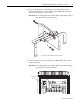
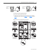
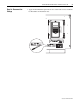
5. Complete the conductivity test between the left and right power structures as
indicated in Table I
below.
Important:If the drive fails any of these measurements, verify that you have
properly connected the bus bar kit using the correct terminals.
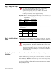
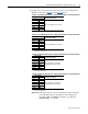
6. Complete the conductivity test on the DC bus as indicated in Table J
below.
Important:If the drive fails any of these measurements, refer to the
Hardware Service Manual for PowerFlex 700S and 700H Drives
(Frame 12), publication PFLEX-TG004…, for troubleshooting
information.
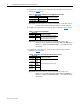
7. Complete the conductivity test on the DC bus to drive chassis ground as
indicated in Table K
below.
Important:If the drive fails any of these measurements, refer to the
Hardware Service Manual for PowerFlex 700S and 700H Drives
(Frame 12), publication PFLEX-TG004…, for troubleshooting
information.
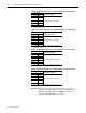
Table I Conductivity Test Between Left and Right Power Structures
Meter Leads
Nominal meter reading+-
+ DC Bus (Left) + DC Bus (Right)
Meter should read 0.000
– DC Bus (Left) – DC Bus (Right)
Table J Conductivity Test on DC Bus
Meter Leads
Nominal meter reading+-
+ DC Bus – DC Bus Meter should gradually rise until leads
are removed. Note: Meter may fall and
transition through zero before rising.
– DC Bus + DC Bus
Table K Conductivity Test on DC Bus to Drive Chassis Ground
Meter Leads
Nominal meter reading+-
+ DC Bus Chassis
Ground
Meter should display “.0L” (zero load).
– DC Bus Chassis
Ground
Chassis
Ground
+ DC Bus
Chassis
Ground
– DC Bus