
Instruction Manual

Publication PFLEX-IN022A-EN-P
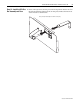
30 PowerFlex® 700S and 700H Frame 12 DC Bus Connector Kit
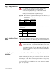
Important:If the drive fails any of these measurements, replace the
appropriate Rectifying Module. Refer to the Hardware Service
Manual for PowerFlex 700S and 700H Drives (Frame 12),
publication PFLEX-TG004…, for details.
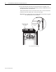
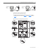
Table A Forward Biased Diode Tests - Rectifying Module for Power Structure #1
Meter Leads
Nominal meter reading-+
DC+/R+
(1)
(1)
If the drive does not contain the brake chopper option, the DC+/R+
terminal will be labeled DC+.
1L1
Meter should beep once and value
should gradually rise to about 0.5V
DC+/R+ 1L2
DC+/R+ 1L3
1L1 DC-
1L2 DC-
1L3 DC-
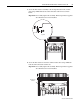
Table B Forward Biased Diode Tests - Rectifying Module for Power Structure #2
Meter Leads
Nominal meter reading-+
DC+/R+
(1)
(1)
If the drive does not contain the brake chopper option, the DC+/R+
terminal will be labeled DC+.
2L1
Meter should beep once and value
should gradually rise to about 0.5V
DC+/R+ 2L2
DC+/R+ 2L3
2L1 DC-
2L2 DC-
2L3 DC-
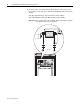
Table C Reverse Biased Diode Tests - Rectifying Module for Power Structure #1
Meter Leads
Nominal meter reading+-
1L1 DC-
Meter should display “.0L” (zero load)
1L2 DC-
1L3 DC-
DC+/R+
(1)
(1)
If the drive does not contain the brake chopper option, the DC+/R+
terminal will be labeled DC+.
1L1
DC+/R+ 1L2
DC+/R+ 1L3
Table D Reverse Biased Diode Tests - Rectifying Module for Power Structure #2
Meter Leads
Nominal meter reading+-
2L1 DC-
Meter should display “.0L” (zero load)
2L2 DC-
2L3 DC-
DC+/R+
(1)
(1)
If the drive does not contain the brake chopper option, the DC+/R+
terminal will be labeled DC+.
2L1
DC+/R+ 2L2
DC+/R+ 2L3