
Instruction Manual

PowerFlex® 700S and 700H Frame 12 DC Bus Connector Kit 29
Publication PFLEX-IN022A-EN-P
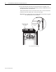
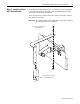
1. Verify that no power is applied to the drive.
2. Disconnect all motor leads from the drive.
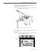
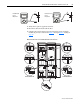
3. Complete the forward and reverse biased diode tests on the rectifying
modules (if present) as indicated in Table A
through Table D starting on
page 30
.
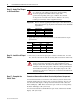
Measurement Points for Forward and Reverse Diode Tests
~.0L
+
-
~0.5V
+
-
Forward biased
test on
PN-junction
Reverse biased
test on
PN-junction
DANGER DANGER
DC BUS CONDUCTORS AND CAPACITORS
OPERATE AT HIGH VOLTAGE. REMOVE POWER
AND WAIT 5 MINUTES BEFORE SERVICING
DANGER DANGER
DC BUS CONDUCTORS AND CAPACITORS
OPERATE AT HIGH VOLTAGE. REMOVE POWER
AND WAIT 5 MINUTES BEFORE SERVICING
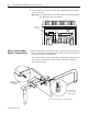
Cat No.
1234567890-*
FIELD INSTALLED OPTIONS:FIELD INSTALLED OPTIONS:
DC- DC+ DC- DC+
1L1
1L2
1L3
2L1
2L2
2L3
1U/T1
1V/T2
1W/T3
2U/T1
2V/T2
2W/T3
Power Structure #1 Power Structure #2