
Instruction Manual

Publication PFLEX-IN022A-EN-P
2 PowerFlex® 700S and 700H Frame 12 DC Bus Connector Kit
What This Kit Includes
• Air flow restriction plate (1)
• Support bracket (2)
• Insulated grommet (2)
• M8 insulated standoff (1)
• M10 insulated standoff (4)
• Rittal TS8 system mounting rail (2) and self tapping screws (8)
• DC+ bus bars (4)
• DC- bus bars (4)
• M4 hardware: M4x16 bolts (16), flat washer (32), lock washer (16), hex nuts
(16)
• M8 hardware: M8x12 bolt (1), M8x16 bolts (1), flat washer (2), lock washer
(2)
• M10 hardware - M10x12 bolt (2), M10x16 bolt (6), M10x25 bolt (6),
M10x30 bolt (8), flat washer (32), lock washer (22), hex nut (10)
• Fuse (2) - Ferraz Shawmut catalog number: PC72UD11C630D1A (630 Amp
IEC@1100V, or UL@1200V)
• Field Installed Option label
Tools That You Need
• Torx head screwdriver
• Phillips head screwdriver
• Torque wrench
• Adjustable wrench
• Multi-meter - Digital multi meter, capable of ac and dc voltage, continuity,
resistance, capacitance measurements, and forward diode bias tests
What You Need To Do
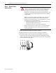
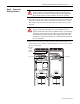
❒ Step 1: Remove power from drive
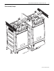
❒ Step 2: Prepare the existing enclosure
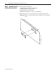
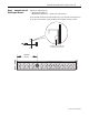
❒ Step 3: Assemble the new air flow restriction plate
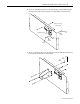
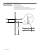
❒ Step 4: Assemble the left side support bracket
❒ Step 5: Assemble the right side support bracket
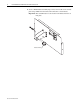
❒ Step 6: Assemble the DC– bus bars
❒ Step 7: Assemble the DC+ bus bars
❒ Step 8: Install the new air flow restriction plate assembly
❒ Step 9: Install the left side mounting rail assembly
❒ Step 10: Install the right side mounting rail assembly
❒ Step 11: Install the DC– bus bar assembly and fuse
❒ Step 12: Install the DC+ bus bar assembly and fuse
❒ Step 13: Install the left side DC+ terminal bus bar
❒ Step 14: Install the right side DC– terminal bus bar
❒ Step 15: Apply final torque to all connections
❒ Step 16: Install the AC input cables
❒ Step 17: Complete the circuit tests
❒ Step 18: Document the change