
User guide


Publication PFLEX-IN023A-EN-P
46
Important: If the drive fails any of these measurements, verify that all
connections have been properly made for the appropriate rectifier
module.
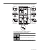
Series B Rectifier Circuit Board - Rectifier Module Tests
Important: If the drive fails any of these measurements, verify that all
connections have been properly made for the appropriate rectifier
module.
Table B Reverse Biased Diode Tests on Rectifier Module(s)
Meter Leads
Nominal meter reading+-
1L1 DC-
Meter should display “.0L” (zero load)
1L2 DC-
1L3 DC-
DC+ 1L1
DC+ 1L2
DC+ 1L3
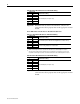
Table C Forward Biased Diode Tests on Rectifier Module(s)
Meter Leads
Nominal meter reading-+
DC+ 1L1
Meter should beep once and value should gradually rise to about 1.0 V
(1)
(1)
The actual voltage reading may vary depending upon your equipment. If your readings are not near 1.0V, verify
that the actual voltage measured is consistent for the Rectifier module and the Output Power modules.
DC+ 1L2
DC+ 1L3
1L1 DC-
The value should gradually rise to about 0.35V
(2)
(2)
The actual voltage reading may vary depending upon your equipment. If your readings are not near 0.35V,
verify that the actual voltage measured is consistent for the Rectifier module and the Output Power modules.
1L2 DC-
1L3 DC-
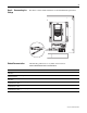
Table D Reverse Biased Diode Tests on Rectifier Module(s)
Meter Leads
Nominal meter reading+-
1L1 DC-
Meter should display “.0L” (zero load)
1L2 DC-
1L3 DC-
DC+ 1L1
DC+ 1L2
DC+ 1L3