
User guide


Publication PFLEX-IN023A-EN-P
26
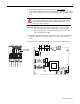
7. Remove the two screws that secure the wires for the ASIC board power
supply to the DC+ and DC- bus bars and disconnect the cables for the fan
power and control from the connectors as indicated below. The fan power
wires connect to the base of the fuse holder on the V phase module.
8. Remove the air flow sheet from below the gate driver boards.
DC-
DC+
Rectifier signal
connectors
Fan signal
connectors
Fan power connections
on fuse holder
ASIC board power
connections
Fan signal
connector
Remove air
flow sheet
Remove screws
PZ2
5.0 N•m
(44.2 lb•in)