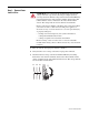
PowerFlex® 700S and 700H Frames 10…12 Rectifier Module Replacement Kit Installation Instructions ATTENTION: To avoid an electric shock hazard, ensure that all power to the drive has been removed before performing the following. ATTENTION: To avoid an electric shock hazard, verify that the voltage on the bus capacitors has discharged completely before servicing.
Important Parts Information Important: Due to a change in the SCR modules used in the rectifier module provided in this kit, the rectifier module DC+ bus bars and insulator material provided in this kit must be used. Therefore, the existing rectifier module DC+ bus bar and insulator material must not be reused when installing this rectifier module kit. See details below.
Bus Bar and Rectifier Module Insulator Material The insulator sheet that is placed between the main DC- and DC+ bus bars for rectifier modules with round SCR terminals is one piece. The insulator material provided with this kit is two pieces, one sheet for between the main DC- and DC+ bus bars and one to cover the rectifier module.
Understanding Torque Figures in Illustrations Icons and numbers in the assembly illustrations indicate how to tighten hardware after re-assembly: Fastener Type: POZIDRIV Screw Hexalobular (TORX) Screw Hexagonal Screw Tool Type and Size: PZ = POZIDRIV screwdriver bit T = Hexalobular (TORX) screwdriver bit xx mm = Socket wrench HEX = Hexagonal screwdriver/bit PZ2 4 N•m (35 lb•in) Tightening Torque Hexagonal Bolt Hexagonal Nut ATTENTION: A hazard of personal injury and/or equipment damage exists if the
Step 1: Remove Power from the Drive ATTENTION: To avoid an electric shock hazard, verify that the voltage on the bus capacitors has discharged completely before servicing. Check the DC bus voltage at the Power Terminal Block by measuring between the +DC and -DC terminals, between the +DC terminal and the chassis, and between the -DC terminal and the chassis. The voltage must be zero for all three measurements. Remove power before making or breaking cable connections.
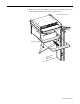
Step 2: Remove the Protective Covers from the Drive To remove the protective covers, you must first move the control frame and then remove the air flow plate. 1. Loosen the T8 hexalobular screws that hold the control frame to the drive enclosure (remove screws on early frame 10 drives). 2. Swing the control frame out and away from the power structure.
3. Remove the four T8 hexalobular screws that secure the airflow plate to the drive and slide the airflow plate off the enclosure frame.
4. Remove the four M5 POZIDRIV screws that secure the top and bottom protective covers to the main front protective cover and remove the top and bottom protective covers. 5. Remove the four M5 POZIDRIV screws that secure the main front protective cover to the drive and remove the protective cover. 6. On frame 10 and 12 drives only, remove the side protective covers. 4 6 4 5 6 5 PZ2 3.0 N•m (26.
Step 3: Remove the Power In order to remove the power structure from the enclosure you must first remove the power and ground wiring. Structure from the Enclosure For terminal locations, refer to Figure 1 below for frame 10 and 12 drives and Figure 2 on page 10 for frame 11 drives. 1. Remove the insulator material from between the input terminals. 2.
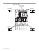
Figure 2 Frame 11 Drives Remove Insulator Material from between Terminals DC Input Power Connection Terminals AC Input Power Connection Terminals 19 mm 40 N•m (354 lb•in) 19 mm 40 N•m (354 lb•in) H Motor Connection Terminals 19 mm 40 N•m (354 lb•in) Publication PFLEX-IN023A-EN-P L H L H L Ground Connection 17 mm 40 N•m (354 lb•in)
5. Remove the bolts that secure the power structure to the drive enclosure (see Figure 3 below for frame 10 and 12 and Figure 4 on page 12 for frame 11). 6. Follow the instructions in the PowerFlex 700S and 700H High Power Maintenance Stand, Installation Instructions, publication PFLEX-IN014, to assemble the maintenance stand. Note: The maintenance stand is designed for removing power structures from drives supplied in Rittal TS8 enclosures only.
Figure 4 Frame 11 Drives Remove bolts H L H L H L Remove bolts The steps for removing the rectifier module(s) from a frame 10 and 12 size drive Step 4: Remove the Existing Rectifier Module(s) are different than a frame 11 size drive. Refer to Remove the Rectifier Module(s) from a Frame 10 or 12 Drive on page 13 or Remove the Rectifier Module from a Frame 11 Drive on page 22.
Remove the Rectifier Module(s) from a Frame 10 or 12 Drive The rectifier module(s) on frame 10 and 12 drives are contained in the right side of the power structure(s). Frame 12 Frame 10 Rectifier module(s) located on right side of power structure(s) Note: Cut any cable ties securing control and power cables as necessary in order to complete the following procedures.
1. Remove the two M4x8 hexalobular screws that secure the control power supply wires to the DC- and DC+ bus bars above the Gate Driver board and remove the wires. 2. Loosen, but do not remove, the eight M10 hex nuts that secure the DC- and DC+ connective bus bars to the drive. Rectifier board DCDC+ Loosen, but do not remove, hex nuts Remove screws T20 1.0 N•m (8.8 lb•in) 17 mm 40 N•m (354 lb•in) 3.
Figure 5 Series A Rectifier Circuit Board X9 X100 X50 X11 X12 X10 X6 X101 X13 X8 T20 1.5 N•m (13.3 lb•in) J3 J7 J11 X3 X41 X1 X2 X4 Figure 6 Series B Rectifier Circuit Board X8 X9 X100 X12 X33 X23 X11 X32 X22 X10 X31 X21 X50 X6 X101 X13 T20 1.5 N•m (13.
4. If the common mode jumper is in the lowered position (as show below), remove the M4x8 hexalobular screw that secures the jumper to the bracket connected to the rectifier board. Important: Note the position of the jumper before removal and ensure that it is placed in the same position when the rectifier board is installed. Top of Power Structure Common mode jumper Rectifier circuit board Do not remove screw at X41 on rectifier circuit board T20 1.5 N•m (13.3 lb•in) Remove screw 5.
7. Remove the six M10x20 bolts and washers that secure the DC- and DC+ rectifier bus bars and power cable to the SCRs on the rectifier module and remove the bus bars and power cable. Important: Do Not reuse the existing DC+ rectifier bus bar.
8. For 400/480V AC input drives, remove the three hexalobular screws that secure the balancing resistor wires to the main bus bars. For 600/690V AC input drives, remove the four hexalobular screws that secure the balancing resistor wires to the main bus bars. Important: Note the color (if unique) and location of each resistor connector wire. Mark all connections and wires before removal to avoid incorrect wiring during reassembly. 400/480V AC Input Drives T20 1.5 N•m (13.
10. Remove the bus bars and insulator sheets from the drive. The steps to remove the bus bars from a 400/480V AC input drive are different than the steps to remove the bus bars from a 600/690V AC input drive. Refer to Remove the Bus Bars from a 400/480V AC Input Drive below or Remove the Bus Bars from a 600/690V AC Input Drive on page 20.
Remove the Bus Bars from a 600/690V AC Input Drive – Remove the four M6x25 hexalobular screws that secure the outer bus bar to the drive and remove the bus bar and the loose bus bar insulator sheet. – Remove the four M6x20 hexalobular screws that secure the next bus bar to the drive and remove the bus bar and the loose bus bar insulator sheet. – Remove the two M6x20 hexalobular screws that secure the main DCbus bar to the drive and remove the main DC- bus bar and the loose bus bar insulator sheet.
11. Remove the eight M4x8 POZIDRIV screws that secure the rectifier module to the drive frame and remove the module. Remove screws PZ2 1.5 N•m (13.3 lb•in) 12. Continue with Step 5: Install the New Rectifier Module on page 43.
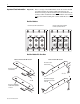
Remove the Rectifier Module from a Frame 11 Drive The rectifier module(s) on frame 11 drives are contained in the V and W phase power structure(s). 690V AC input 460A and 502A frame 11 drives only have one rectifier module contained in the V phase power structure. U Phase V Phase W Phase H L H L H L Rectifier modules located on sides of power structures Note: Cut any cable ties securing control and power cables as necessary in order to complete the following procedures.
ATTENTION: The sheet metal cover and mounting screws on the ASIC Board located on the power structure are energized at (-) DC bus potential high voltage. Risk of electrical shock, injury, or death exists if someone comes into contact with the assembly. 1. Remove the four M4x8 POZIDRIV screws that secure the ASIC board cover to the assembly and lift the cover off the assembly - you must unplug the cable for the ASIC board assembly fan from connector X1 on the ASIC board in order to remove the cover.
2. Carefully disconnect the fiber-optic cables from sockets H1…H13 of the ASIC board and carefully set them aside (see illustration below). ATTENTION: Hazard of permanent eye damage exists when using optical transmission equipment. This product emits intense light and invisible radiation. Do not look into fiber-optic ports or fiber-optic cable connectors. Important: Minimum inside bend radius for fiber-optic cable is 25.4 mm (1.0 in.).
5. Carefully disconnect the fiber-optic cables from sockets H15 and H16 on each of the three gate driver boards and carefully set them aside (see illustration below). ATTENTION: Hazard of permanent eye damage exists when using optical transmission equipment. This product emits intense light and invisible radiation. Do not look into fiber-optic ports or fiber-optic cable connectors. Important: Minimum inside bend radius for fiber-optic cable is 25.4 mm (1.0 in.).
7. Remove the two screws that secure the wires for the ASIC board power supply to the DC+ and DC- bus bars and disconnect the cables for the fan power and control from the connectors as indicated below. The fan power wires connect to the base of the fuse holder on the V phase module. 8. Remove the air flow sheet from below the gate driver boards. ASIC board power connections DC- Remove screws Rectifier signal connectors DC+ Remove air flow sheet PZ2 5.0 N•m (44.
9. For PowerFlex 700H drives, continue with step 12 on page 28. For PowerFlex 700S drives only, carefully disconnect the fiber-optic cables from sockets J4 and J5 on the voltage feedback board and carefully set them aside. ATTENTION: Hazard of permanent eye damage exists when using optical transmission equipment. This product emits intense light and invisible radiation. Do not look into fiber-optic ports or fiber-optic cable connectors. Important: Minimum inside bend radius for fiber-optic cable is 25.
12. The V and W phase modules must be removed from the power structure in order to remove the rectifier modules. Therefore, you must lift the power structure off the maintenance stand and place it, rear side of the unit down, on a clean, suitable work surface. Follow the steps below to lift and move the power structure. a. Fasten the lifting hardware to the holes in the flanges on the top of the power structure, symmetrically, in at least two holes.
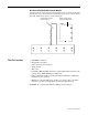
13. For drives with DC bus supply terminals, remove the six M10 nuts and washers that secure the bus bars that connect the DC– and DC+ terminals to the horizontal bus bars and remove the bus bars. DC- DC+ Remove nuts 17 mm 40 N•m (354 lb•in) Remove bus bars Remove nuts 17 mm 40 N•m (354 lb•in) Note: Power cables not shown for clarity only.
14. Remove the four M10 bolts and washers that secure the power cables to the rectifier circuit output terminals. 15. Remove the four M10 nuts and washers that secure the other end of the power cables to the DC– and DC+ collector bus bars and remove the cables.
16. Remove the four remaining nuts and washers that secure the DC– and DC+ collector bus bars to the drive, and remove the bus bars and insulator material between them. Important: The insulator material must be installed between the bus bars during installation.
17. Remove the six M10 nuts and washers that secure the AC supply cables to the AC input terminals and remove the cables. Note: Frame 11 690V AC input, 460A and 502A drives, only have one set of AC input terminals and therefore one set of AC supply cables.
18. Remove the eight POZIDRIV screws that secure the terminal assembly to the drive and remove the assembly. PZ2 4.0 N•m (35.
19. Remove the four M10 hexagonal screws that secure each of the V and W phase modules to the drive frame.
20. Remove the six M5 and six M6 POZIDRIV screws that secure the upper sheet metal plate of the power structure frame to the lower frame and remove the upper metal plate. Remove M5 screws Remove M6 screws PZ2 5.0 N•m (44.3 lb•in) Remove M5 screws Remove M6 screws PZ3 5.0 N•m (44.3 lb•in) 21. Carefully remove the phase module from the top of the drive frame. 22.
Figure 7 Series A Rectifier Circuit Board X9 X100 X50 X11 X12 X10 X6 X101 X13 X8 T20 1.5 N•m (13.3 lb•in) J3 J7 J11 X3 X41 X1 X2 X4 Figure 8 Series B Rectifier Circuit Board X8 X9 X100 X12 X33 X23 X11 X32 X22 X10 X31 X21 X50 X6 X101 X13 T20 1.5 N•m (13.
23. If the common mode jumper is in the lowered position (as show below), remove the M4x8 hexalobular screw that secures the jumper to the bracket connected to the rectifier board. Important: Note the position of the jumper before removal and ensure that it is placed in the same position when the rectifier board is installed. Top of Power Structure Common mode jumper Rectifier circuit board Do not remove screw at X41 on rectifier circuit board T20 1.5 N•m (13.3 lb•in) Remove screw 24.
26. Remove the M10 bolts and washers that secure the AC input supply cables and SCR terminal bus bars to the rectifier module and remove the cables and bus bars from the rectifier module. Remove bolts 17 mm 12 N•m (106 lb•in) AC supply cables Terminal bus bars 27. Remove the six M10x20 bolts and washers that secure the DC- and DC+ rectifier bus bars to the rectifier module and remove the bus bars. Important: Do Not reuse the existing DC+ rectifier bus bar.
28. For 400/480V AC input drives, remove the three hexalobular screws that secure the balancing resistor wires to the main bus bars. For 600/690V AC input drives, remove the four hexalobular screws that secure the balancing resistor wires to the main bus bars. Important: Note the color (if unique) and location of each resistor connector wire. Mark all connections and wires before removal to avoid incorrect wiring during reassembly. 400/480V AC Input Drives T20 1.5 N•m (13.
30. Remove the bus bars and insulator sheets - the steps to remove the bus bars from a 400/480V AC input drive are different than the steps to remove the bus bars from a 600/690V AC input drive. Refer to Remove the Bus Bars from a 400/480V AC Input Drive below or Remove the Bus Bars from a 600/690V AC Input Drive on page 41.
Remove the Bus Bars from a 600/690V AC Input Drive – Remove the four M6x25 hexalobular screws that secure the outer bus bar to the drive and remove the bus bar and the loose bus bar insulator sheet. – Remove the four M6x20 hexalobular screws that secure the next bus bar to the drive and remove the bus bar and the loose bus bar insulator sheet. – Remove the two M6x20 hexalobular screws that secure the main DCbus bar to the drive and remove the main DC- bus bar and the loose bus bar insulator sheet.
31. Remove the eight M4x8 POZIDRIV screws that secure the rectifier module to the drive frame and remove the module. Remove screws PZ2 1.5 N•m (13.3 lb•in) 32. Continue with Step 5: Install the New Rectifier Module below.
Step 5: Install the New Rectifier Module Install the new rectifier module, in the reverse order of removal. Refer to Step 4: Remove the Existing Rectifier Module(s) on page 12. ATTENTION: A hazard of personal injury and/or equipment damage exists if the rectifier DC+ bus bar for round SCR terminals is installed on the rectifier module provided with this kit. Do Not reuse the rectifier DC+ bus bar that was used on the round SCR terminals and install the rectifier DC+ bus bar provided with this kit only.
Step 6: Install the Power Structure in the Enclosure Install the power structure in the drive enclosure in the reverse order of removal. Refer to Step 3: Remove the Power Structure from the Enclosure on page 9. Step 7: Complete the Circuit Tests Forward and Reverse Biased Diode Tests for Major Power Components A forward biased diode test checks the semiconductor junctions between the terminals and measures the voltage drop across those junctions.
Measurement Points for Forward and Reverse Diode Tests Frame 10 and 12 Drives DC- DC+ DC- DC+ Cat No. FIELD INSTALLED OPTIONS: DANGER DC BUS CONDUCTORS AND CAPACITORS OPERATE AT HIGH VOLTAGE. REMOVE POWER AND WAIT 5 MINUTES BEFORE SERVICING 1U/T1 2V/T2 1234567890-* 1V/T2 DANGER DC BUS CONDUCTORS AND CAPACITORS OPERATE AT HIGH VOLTAGE.
Table B Reverse Biased Diode Tests on Rectifier Module(s) Meter Leads + 1L1 DC1L2 DC1L3 DCDC+ 1L1 DC+ 1L2 DC+ 1L3 Nominal meter reading Meter should display “.0L” (zero load) Important: If the drive fails any of these measurements, verify that all connections have been properly made for the appropriate rectifier module.
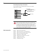
Measurement Points for Forward and Reverse Diode Tests Frame 11 Drives Figure 9 Measurement Points for Forward and Reverse Diode Tests DC+ DC- U/T1 1L1 V/T2 1L3 1L2 W/T3 2L1 2L3 2L2 Note: 600V ac input, 460A and 502A frame 11 drives only have one rectifier module.
Table F Reverse Biased Diode Tests on Rectifier Module(s) Meter Leads + L1 DCL2 DCL3 DCDC+ L1 DC+ L2 DC+ L3 Nominal meter reading The meter should display “.0L” (zero load) Important: If the drive fails any of these measurements, verify that all connections have been properly made for the appropriate rectifier module.
Step 9: Documenting the Change Record the rectifier module installation on the Field Installed Option label. Related Documentation Allen-Bradley publications are available on the internet at www.rockwellautomation.com/literature.
U.S. Allen-Bradley Drives Technical Support - Tel: (1) 262.512.8176, Fax: (1) 262.512.2222, Email: support@drives.ra.rockwell.com, Online: www.ab.com/support/abdrives www.rockwellautomation.com Power, Control and Information Solutions Headquarters Americas: Rockwell Automation, 1201 South Second Street, Milwaukee, WI 53204 USA,Tel: (1) 414.382.2000, Fax: (1) 414.382.