
Instruction Manual

Table Of Contents
- PowerFlex 700S High Performance AC Drive - Phase II Control, Programming Manual
- Summary of Changes
- Table of Contents
- Preface
- Chapter 1 - Drive Start-Up
- Chapter 2 - Programming and Parameters
- Chapter 3 - Troubleshooting
- Appendix A - Human Interface Module Overview
- Appendix B - Application Notes
- Appendix C - Control Block Diagrams
- Appendix D - PowerFlex 700S Permanent Magnet Motor Specifications
- Appendix E - ATEX Approved PowerFlex 700S, Phase II Drives in Group II Category (2) Applications with ATEX Approved Motors
- Appendix F - History of Changes
- Index
- Back Cover
Rockwell Automation Publication 20D-PM001C-EN-P - July 2013 23
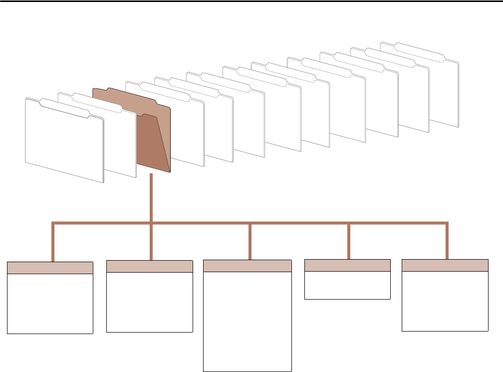
Programming and Parameters Chapter 2
User Functions
Inputs & Outputs
Communication
Utility
Speed/Posit Fdbk
Position Control
Process Control
Torque Control
Speed Control
Dynamic Control
Motor Control
Monitor
Configuration
151
152
153
158
160
169
335
Logic Command
Applied LogicCmd
Control Options
Drive Logic Rslt
Zero Speed Lim
SrLss ZeroSpdLim
Abs OverSpd Lim
Overload Protect
337
338
339
340
341
343
344
Mtr I2T Curr Min
Mtr I2T Spd Min
Mtr I2T Calibrat
Mtr I2T Trp ThrH
Mtr I2T Count
OL OpnLp CurrLim
OL ClsLp CurrLim
Stop/Brake Modes
168
414
415
416
417
154
545
546
547
1125
544
1126
Normal Stop Mode
Brake/Bus Cnfg
BusReg/Brake Ref
Brake PulseWatts
Brake Watts
Stop Dwell Time
Bus Reg Ki
Bus Reg Kp
Bus Reg Kd
DC Brake Level
External DB Res
DC Brake Time
Power Loss
406
407
408
Power Loss Mode
Power Loss Time
Power Loss Level
Sleep/Wake
278
279
280
281
282
283
284
Sleep-Wake Mode
Sleep-Wake Ref
Wake Level
Wake Time
Sleep Level
Sleep Time
Sleep Control