
Instruction Manual
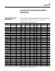
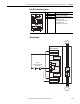
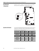
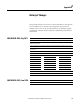
Table Of Contents
- PowerFlex 700S High Performance AC Drive - Phase II Control, Programming Manual
- Summary of Changes
- Table of Contents
- Preface
- Chapter 1 - Drive Start-Up
- Chapter 2 - Programming and Parameters
- Chapter 3 - Troubleshooting
- Appendix A - Human Interface Module Overview
- Appendix B - Application Notes
- Appendix C - Control Block Diagrams
- Appendix D - PowerFlex 700S Permanent Magnet Motor Specifications
- Appendix E - ATEX Approved PowerFlex 700S, Phase II Drives in Group II Category (2) Applications with ATEX Approved Motors
- Appendix F - History of Changes
- Index
- Back Cover
Rockwell Automation Publication 20D-PM001C-EN-P - July 2013 207
ATEX Approved PowerFlex 700S, Phase II Drives in Group II Category (2) Applications with ATEX Approved Motors Appendix E
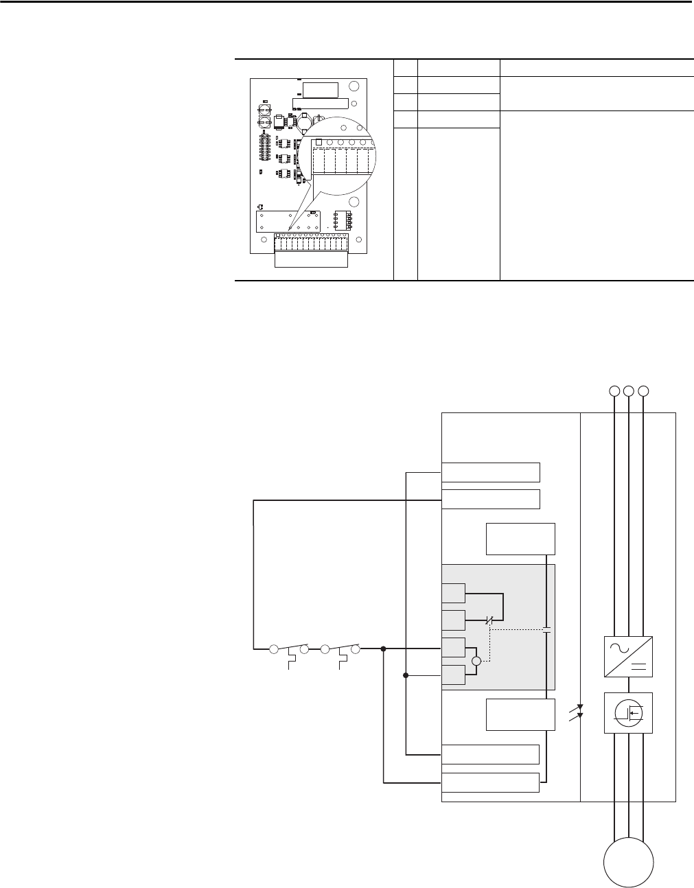
Safe-Off Terminal Descriptions
Wiring Example
No. Signal Description
1 +24V DC Connections for power to energize coil.
33.3 mA typical, 55 mA maximum.
2 24V Common
3 Monitor - N.C. Normally closed contacts for monitoring relay
status.
Maximum Resistive Load:
250V AC / 30V DC / 50 VA / 60 Watts
Maximum Inductive Load:
250V AC / 30V DC / 25 VA / 30 Watts
4 Common - N.C.
12345678910 131211
123456
24V DC Common
PowerFlex 700S
Phase II AC Drive
+24V DC
1
2
13
16
3
4
1
2
Safe Off Option
AC Line
Input Power
Digital In 6 (Enable)
Digital In 4-6 Com.
M
Gate Control
Power Supply
Gate Control
Circuit
Motor
Over Temperature
Sensor(s)