
Instruction Manual
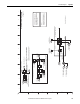
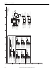
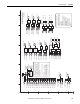
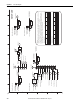
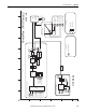
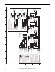
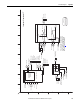
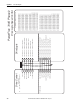
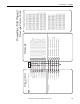
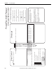
Table Of Contents
- PowerFlex 700S High Performance AC Drive - Phase II Control, Programming Manual
- Summary of Changes
- Table of Contents
- Preface
- Chapter 1 - Drive Start-Up
- Chapter 2 - Programming and Parameters
- Chapter 3 - Troubleshooting
- Appendix A - Human Interface Module Overview
- Appendix B - Application Notes
- Appendix C - Control Block Diagrams
- Appendix D - PowerFlex 700S Permanent Magnet Motor Specifications
- Appendix E - ATEX Approved PowerFlex 700S, Phase II Drives in Group II Category (2) Applications with ATEX Approved Motors
- Appendix F - History of Changes
- Index
- Back Cover
Rockwell Automation Publication 20D-PM001C-EN-P - July 2013 197
Control Block Diagrams Appendix C
inverter_ovrload_IT.eps
Mtr Over Load (I
2
T)
60
1.0
pu_current
pu_current
2.0 typ
right of curve
1.025 typ
time (sec)
pu motor
velocity
DB resistor
dc bus
415
417
416
414
321
0
5
1
Brake PulseWatts
{pulse watts @ 1sec}
Brake Watts
Exception Event 2
(BrakeOL Trip )
BusReg/Brake Ref
{% of peak ac line }
Brake/Bus Cnfg
(Brake Enable)
pu Stator Current fdbk
Mtr I2T Calibrat
Mtr I2T Trp ThrH
Mtr OL Factor
Mtr I2T Curr Min
337
336
339
340
320 10
11
Exception Event 1
(Mtr OL Trip)
(Mtr OL Pend )
338
Mtr I2T Spd Min
Inverter Overload IT
Heat sink and
Junction degree
Calculator
Inverter Over Load (IT)
0
1
2
3
4
5
6
7
NTC
Pwr EE Data
Iq Ref Limited
(see torque block)
313
345
343
344
346
Drive OL Status
OL OpnLP CurrLim
Heatsink Temp
Drive OL JnctTemp
(NTC Open)
(HS OverTemp )
OL ClsLp CurrLim
(NTC Shorted )
(IT Pending)
(IT Foldback )
(HS Pending )
(IT Trip)
(Jnc OverTemp)
(Inv OTmpTrip0
(Inv OL Pend)
(Inv OTmpPend )
(Inv OLTrip)
320
355
(Brake Extern )
Exception Event 1
Duty Cycle
Bus Voltage
PWM Frequency
Power Device
Characteristics
13
14
16
15
308
X
2Motor NP FLA
Output Current
1
2
3
4
5
6
BA
D
C
FE HG
I
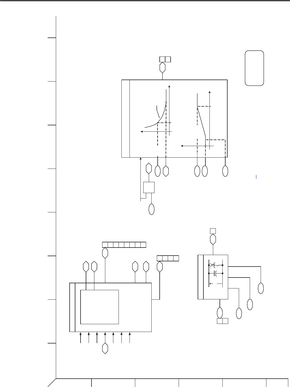
TestPoints
P347 Drive OL TP Sel
P348 Drive OL TP Data
Note: Set this parameter to the minimum
value for the motor overload trip to vary
in time at low speeds. See Mtr I2T Spd
Min on page 69
for more information.