
Instruction Manual
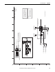
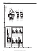
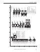
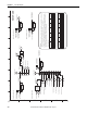
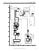
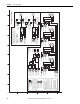
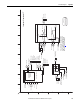
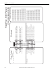
Table Of Contents
- PowerFlex 700S High Performance AC Drive - Phase II Control, Programming Manual
- Summary of Changes
- Table of Contents
- Preface
- Chapter 1 - Drive Start-Up
- Chapter 2 - Programming and Parameters
- Chapter 3 - Troubleshooting
- Appendix A - Human Interface Module Overview
- Appendix B - Application Notes
- Appendix C - Control Block Diagrams
- Appendix D - PowerFlex 700S Permanent Magnet Motor Specifications
- Appendix E - ATEX Approved PowerFlex 700S, Phase II Drives in Group II Category (2) Applications with ATEX Approved Motors
- Appendix F - History of Changes
- Index
- Back Cover
Rockwell Automation Publication 20D-PM001C-EN-P - July 2013 195
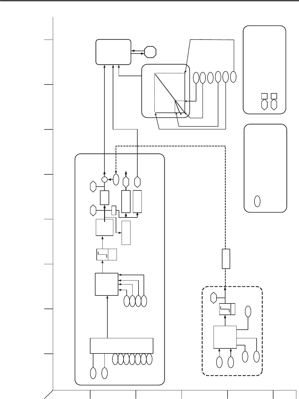
Control Block Diagrams Appendix C
V_Hz.eps
PowerFlex 700S Phase 2
Volts / Hz
V/Hz
Current
Processing
Motor
V/Hz Mode
540 0
540 1
V/Hz Status
Current Lim
Bus Volt Lim
Speed
Ref
Selection
Lead
Lag
4643
Friction Comp
Inertia Comp
Speed Control - Reference (Task 2)
69
55
Ramped Spd Ref Scaled Spd Ref
27
28
15
16
17
18
20
19
Speed Ref A Sel
Speed Ref B Sel
Preset Spd 2
Preset Spd 3
Preset Spd 4
Preset Spd 5
Preset Spd 6
Preset Spd 7
Virtual Encoder
+
21
Speed Trim 1
Linear
Ramp &
S Curve
Link
PI Regulator
181
182
PI Reference
PI Feedback
Limit
186
187
PI Prop Gain
PI Integ Time
Process Control (Task 2)
180
PI Output
184
PI Lpass Filt BW
V/Hz Control
485
Motor Ctrl Mode = 3
Link (not a
default link )
14
Preset Spd 1
Skip Freq
136
137
Skip Speed 1
Skip Speed 2
139
Skip Speed Band
Limit
138Skip Speed 3
V/HZ Boost
527
Start/Acc Boost
528
Run Boost
529
Break Voltage
530
Break Freq
531
Max Voltage
532
Max Freq
V
Hz
1
2
3
4
5
6
BA
D
C
FE HG
I