
Instruction Manual
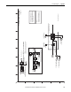
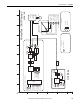
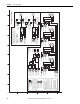
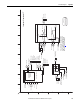
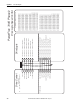
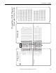
Table Of Contents
- PowerFlex 700S High Performance AC Drive - Phase II Control, Programming Manual
- Summary of Changes
- Table of Contents
- Preface
- Chapter 1 - Drive Start-Up
- Chapter 2 - Programming and Parameters
- Chapter 3 - Troubleshooting
- Appendix A - Human Interface Module Overview
- Appendix B - Application Notes
- Appendix C - Control Block Diagrams
- Appendix D - PowerFlex 700S Permanent Magnet Motor Specifications
- Appendix E - ATEX Approved PowerFlex 700S, Phase II Drives in Group II Category (2) Applications with ATEX Approved Motors
- Appendix F - History of Changes
- Index
- Back Cover
194 Rockwell Automation Publication 20D-PM001C-EN-P - July 2013
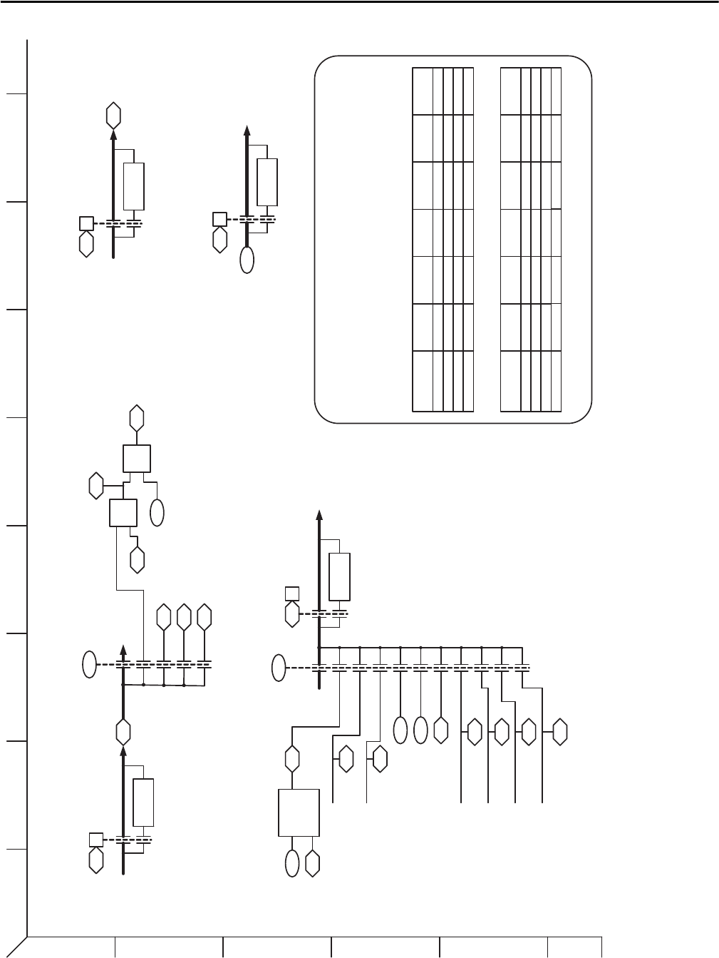
Appendix C Control Block Diagrams
Synchlink.eps
SynchLink
SL Rx Direct Sel 0
0
1
2
3
10
906
SL Rx P0 Regis
SL Rx P1 Regis
917
918
SL Rcv Events
/
SL Mult Base
SL Dir Data Rx 00
929
923
X
924
SL Mult A In
925
SL Mult B In
SL Mult Out
926
0
1
911
SL Tx DirectSel 0
2
3
10
21
22
23
24
25
26
965SL Dir Data Tx 00
929
SL Dir Data Rx 00
Convert
Real-DInt
x Base
922921SL Real2Dint In
SL Mult Base
SL Real2Dint Out
923
From Encdr 0 Accum
From Encdr 1 Accum
From Fdbk Opt 0 Accum
From Fdbk Opt 1 Accum
0
915
SL Clr Events 916
230
Encdr0 Position
240Encdr1 Position
250
FB Opt0 Posit
252FB Opt1 Posit
From Registration Latch 0
From Registration Latch 1
235
RegisLtch 0 Value
239
RegisLtch 1 Value
SL Dir Tx Word 00
to SL Hardware
Use P 929
Directly
Rx Word 00
from SL Hardware
965SL Buf Data Tx 00
SL Buf Tx Word 00
to SL Hardware
929
SL Buf Rx Word 00
from SL Hardware
SL Buf Data Rx 00
Tx Dir Data Type
(SLDir00 Real)
0
1
Convert
Real-DInt
00
Rx Dir Data Type
(SLDir00 Real)
0
1
Convert
Dint-Real
00
Rx Buf Data Type
(SLBuf00 Real)
0
1
Convert
Dint-Real
Tx Buf Data Type
(SLBuf00 Real)
0
1
Convert
Real-DInt
928
933
00969
00964
Direct Receive Data*
Direct Transmit Data*
Buffered Transmit Data*
Buffered Receive Data*
* Notes
There are a total of 4 Direct Receive Words , 4 Direct Transmit Words , 18 Buffered Receive Words, and
18 Buffered Transmit Words. This diagram only shows Word 00 of each type .
Parameters 905 [SL Rx CommFormat] and 910 [SL Tx CommFormat] set the format for the receive
and transmit data. The following tables show the different formats for transmit and receive data and the
respective SynchLink fiber update rates for the direct and buffered data.
Receive Data Format:
0
Parameter 910 [SL
Tx CommFormat]
# of Axis* Axis Update
# of Direct
Words
Direct Word
Update
# of Buffered
Words
Buffered Word
Update
7
9
17
NA 4
4NA0
0
NA 2 50 uSec
8 0.5 mSec
1 mSec1850 uSec
50 uSec
18 0.5 mSec
0
Parameter 905 [SL
Rx CommFormat]
# of Axis* Axis Update
# of Direct
Words
Direct Word
Update
# of Buffered
Words
Buffered Word
Update
7
9
17
14
NA 4
4NA
1ms 31
0
0
NA 2 50 uSec
8 0.5 mSec
1 mSec18
14 1 mSec50 uSec
50 uSec
50 uSec
18 0.5 mSec
Transmit Data Format:
1
2
3
4
5
6
BA
D
C
FE HG
I
14 31ms1 1ms1450