
Instruction Manual
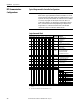
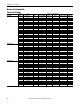
Table Of Contents
- PowerFlex 700S High Performance AC Drive - Phase II Control, Programming Manual
- Summary of Changes
- Table of Contents
- Preface
- Chapter 1 - Drive Start-Up
- Chapter 2 - Programming and Parameters
- Chapter 3 - Troubleshooting
- Appendix A - Human Interface Module Overview
- Appendix B - Application Notes
- Appendix C - Control Block Diagrams
- Appendix D - PowerFlex 700S Permanent Magnet Motor Specifications
- Appendix E - ATEX Approved PowerFlex 700S, Phase II Drives in Group II Category (2) Applications with ATEX Approved Motors
- Appendix F - History of Changes
- Index
- Back Cover
162 Rockwell Automation Publication 20D-PM001C-EN-P - July 2013
Appendix B Application Notes
DPI Communication
Configurations
Typical Programmable Controller Configurations
Logic Command Word
IMPORTANT
If programs are written that continuously write information to the drive, care
must be taken to properly format the block transfer. If attribute 10 is selected
for the block transfer, values will be written only to RAM and will not be saved
by the drive. This is the preferred attribute for continuous transfers. If attribute
9 is selected, each program scan will complete a write to the drives non-
volatile memory (EEprom). Since the EEprom has a fixed number of allowed
writes, continuous block transfers will quickly damage the EEprom. Do Not
assign attribute 9 to continuous block transfers. Refer to the individual
communications adapter User Manual for additional details.
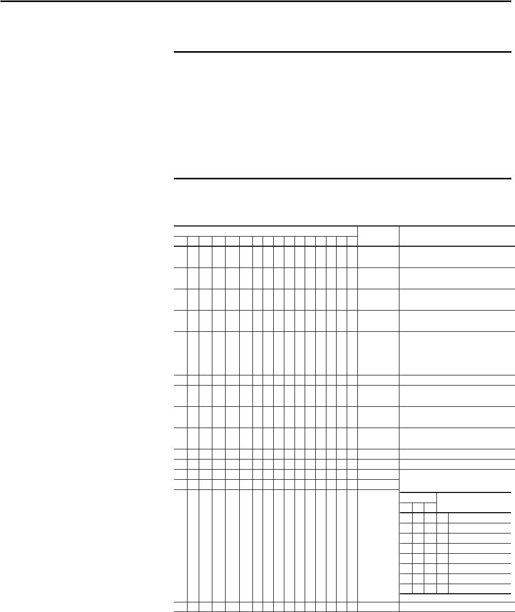
Logic Bits
15 14 13 12 11 10 9 8 7 6 5 4 3 2 1 0 Command Description
x Normal Stop 0 = Not Normal Stop
1 = Normal Stop
xStart
(1)
(1) A Not Stop condition (logic bit 0 = 0, logic bit 8 = 0, and logic bit 9 = 0) must first be present before a 1 = Start condition will start
the drive.
0 = Not Start
1 = Start
x Jog 1 0 = Not Jog using [Jog Speed 1]
1 = Jog using [Jog Speed 1]
xClear Fault
(2)
(2) To perform this command, the value must switch from “0” to “1”.
0 = Not Clear Fault
1 = Clear Fault
x x Unipolar
Direction
00 = No Command
01 = Forward Command
10 = Reverse Command
11 = Hold Direction Control
xReserved
x Jog 2 0 = Not Jog using [Jog Speed 2]
1 = Jog using [Jog Speed 2]
x Current Limit
Stop
0 = Not Current Limit Stop
1 = Current Limit Stop
x Coast Stop 0 = Not Coast to Stop
1 = Coast to Stop
xReserved
xReserved
x Spd Ref l0
x Spd Ref l1
x Spd Ref l2
xReserved
Bits
14 13 12
000=Spd Ref A
001=Spd Ref B
0 1 0 = Preset 2
0 1 1 = Ref. 3 (Preset 3)
1 0 0 = Ref. 4 (Preset 4)
1 0 1 = Ref. 5 (Preset 5)
1 1 0 = Ref. 6 (Preset 6)
1 1 1 = Ref. 7 (Preset 7)