
Instruction Manual
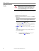
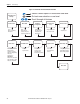
Table Of Contents
- PowerFlex 700S High Performance AC Drive - Phase II Control, Programming Manual
- Summary of Changes
- Table of Contents
- Preface
- Chapter 1 - Drive Start-Up
- Chapter 2 - Programming and Parameters
- Chapter 3 - Troubleshooting
- Appendix A - Human Interface Module Overview
- Appendix B - Application Notes
- Appendix C - Control Block Diagrams
- Appendix D - PowerFlex 700S Permanent Magnet Motor Specifications
- Appendix E - ATEX Approved PowerFlex 700S, Phase II Drives in Group II Category (2) Applications with ATEX Approved Motors
- Appendix F - History of Changes
- Index
- Back Cover
Rockwell Automation Publication 20D-PM001C-EN-P - July 2013 15
Drive Start-Up Chapter 1
Start Up the Drive
6. Press Enter ( ) on the HIM.
The Assisted Start routine will prompt you for the required information
needed to start-up the drive and complete the autotuning procedures. See
Figure 1
on page 16 for a flow chart of the Assisted Start routine.
Note: When starting up some high impedance motor applications, the
“Power Circuit Test” may fail. If this test fails, the HIM displays the
following fault description text:
• Power Circuit Diagnostic Test Detected Error: XX_XX no gate, open
circuit, bad I sensor, press Enter.
If this failure occurs, do the following:
• Verify the connections between the motor and the drive; make sure that
a disconnect device or contactor is not interfering with the signal.
• Press Enter to continue and perform the Direction Test. If the
Direction Test is successful, continue with the Start-Up routine -
ignoring the failure. If the Direction Test fails, check for an open
connection or bad current sensor.
7. When the Assisted Start routine is finished and Done/Exit displays on the
HIM, press Enter ( ) to save any changed and/or updated data.
IMPORTANT
Always exit the Assisted Start routine before cycling power to the drive.