
Instruction Manual
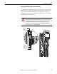
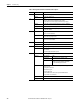
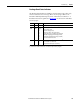
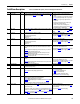
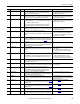
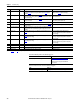
Table Of Contents
- PowerFlex 700S High Performance AC Drive - Phase II Control, Programming Manual
- Summary of Changes
- Table of Contents
- Preface
- Chapter 1 - Drive Start-Up
- Chapter 2 - Programming and Parameters
- Chapter 3 - Troubleshooting
- Appendix A - Human Interface Module Overview
- Appendix B - Application Notes
- Appendix C - Control Block Diagrams
- Appendix D - PowerFlex 700S Permanent Magnet Motor Specifications
- Appendix E - ATEX Approved PowerFlex 700S, Phase II Drives in Group II Category (2) Applications with ATEX Approved Motors
- Appendix F - History of Changes
- Index
- Back Cover
Rockwell Automation Publication 20D-PM001C-EN-P - July 2013 143
Troubleshooting Chapter 3
Precharge Board Status Indicators
The Precharge Board indicators (LEDs) are found on Frame 5 & 6 drives only
and are located above the “Line Type” Phase selection jumper. Refer to the
PowerFlex 700S Adjustable Frequency Drive - Phase II Control, Frames 1…6
Installation Instructions, publication 20D-IN024
, for the location of the Phase
selection jumper.
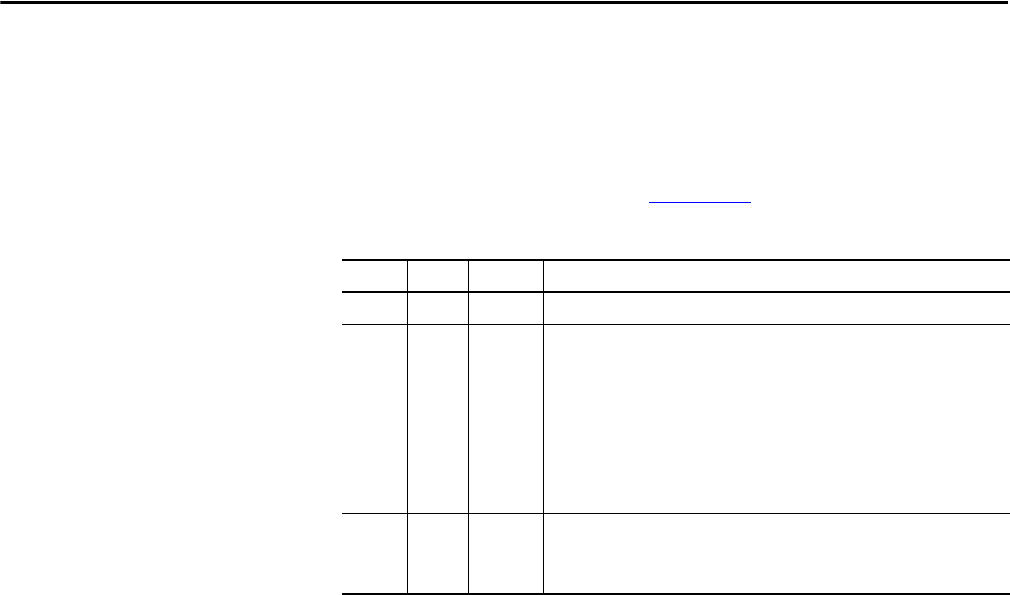
Name Color State Description
Power Green Steady Indicates when precharge board power supply is operational
Alarm Yellow Flashing
[1]
[2]
[3]
[4]
[5]
[6]
[7]
Number in “[ ]” indicates flashes and associated alarm
(1)
:
Low line voltage (<90%).
Very low line voltage (<50%).
Low phase (one phase <80% of line voltage).
Frequency out of range or asymmetry (line sync failed).
Low DC bus voltage (triggers ride-through operation).
Input frequency momentarily out of range (40-65 Hz).
DC bus short circuit detection active.
(1) An alarm condition automatically resets when the condition no longer exists
Fault Red Flashing
[2]
[4]
Number in “[ ]” indicates flashes and associated fault
(2)
:
DC bus short (Udc <2% after 20 ms).
Line sync failed or low line (Uac <50% Unom).
(2) A fault indicates a malfunction that must be corrected and can only be reset after cycling power.